6.1.3 - Capacitor charging and discharging
A capacitor charges and discharges at a changing rate because the potential difference across it changes the circuit current. This lesson explains exponential charge and discharge curves, calculations using the time constant, natural-logarithm plots, and spreadsheet models of discharge.
What changes in an RC circuit
In this lesson, an RC circuit means a capacitor and a resistor connected so that the capacitor charges or discharges through the resistor. The resistor is not just a spare component: it controls the size of the current and therefore controls how quickly charge can move.
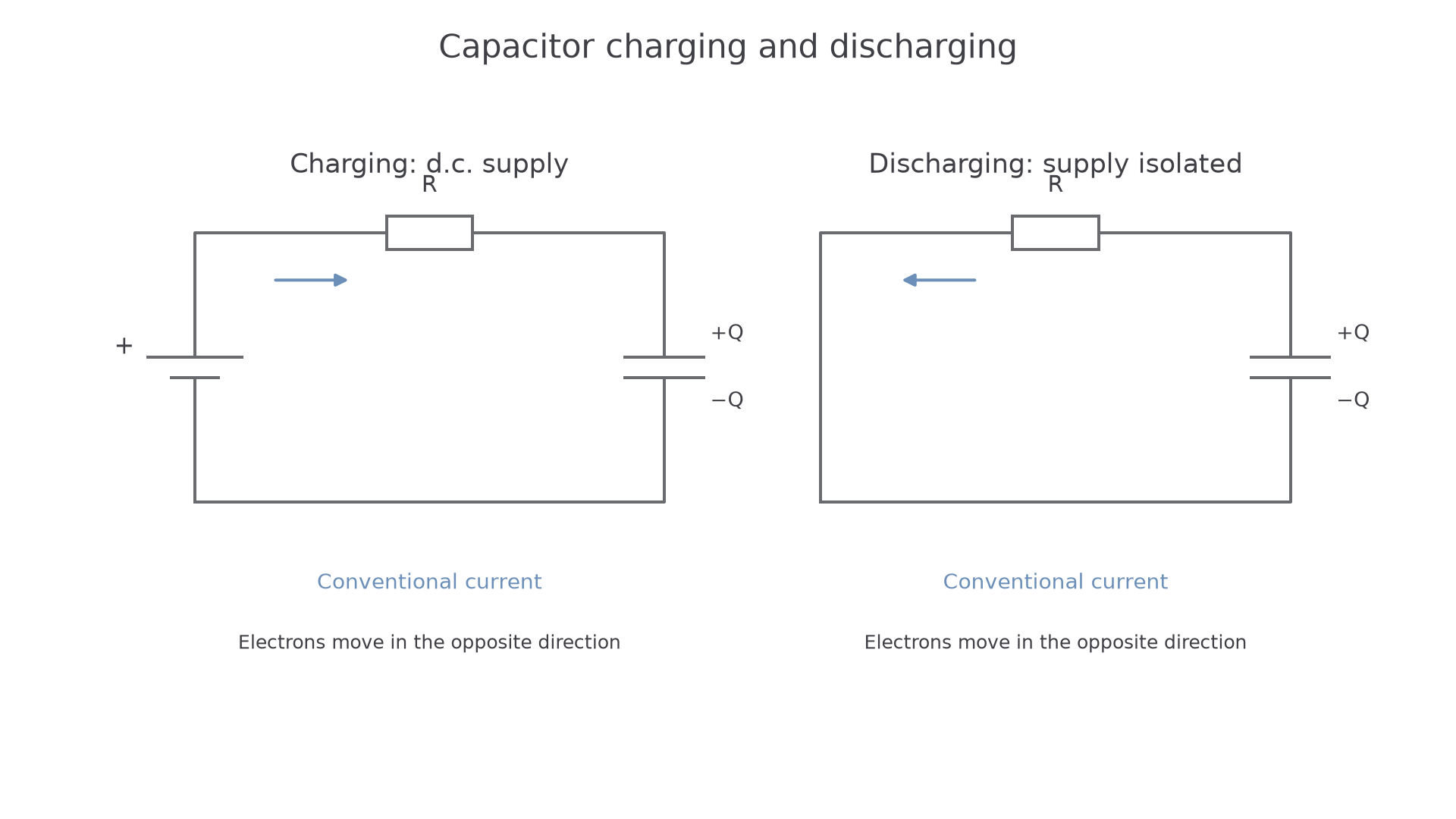
When an uncharged capacitor is connected to a d.c. supply through a resistor, the p.d. across the capacitor is initially zero. The supply p.d. is therefore mainly across the resistor, so the initial current is as large as it can be for that circuit:
where is the supply p.d. and is the resistance. As charge builds up on the capacitor plates, the capacitor p.d. increases. That leaves a smaller p.d. across the resistor, so the current decreases. Eventually the capacitor p.d. is equal to the supply p.d. and the current is zero.
When a charged capacitor is disconnected from the supply and connected through a resistor, it discharges. The capacitor now acts as the source of p.d. for the discharge current. The current is initially large, in the opposite direction to the charging current if you keep the same sign convention, and then falls towards zero as the capacitor loses charge.
The most useful quantities to measure are the p.d. across the capacitor and the time since the switch was moved. If the capacitance is known, the charge is then found from .
The rate is largest at the start because the driving p.d. across the resistor is largest at the start.
During charging, do not say that the resistor "charges up". The resistor has a p.d. across it while current flows; the capacitor is the component that stores separated charge.
[DIAGRAM: asset_name: 6.1.3 - Capacitor charging and discharging - diagram 1; asset_slug: 6_01_3_capacitor_charging_and_discharging__diagram_01; recommended_method: drawn_physics; caption: The supply charges the capacitor, while the isolated capacitor discharges through the resistor.; description: Supply-connected charging and isolated discharge paths showing opposite conventional currents.]
Time constant and exponential equations
The time scale of the charge or discharge is set by the product of resistance and capacitance.
Time constant
The time constant of a capacitor-resistor circuit is . For discharge, it is the time taken for charge, p.d. or current magnitude to fall to , about 37%, of its initial value.
The unit check is useful:
So a larger resistor or a larger capacitor gives a larger time constant and a slower change.
RC time constant
For a quantity that is decaying towards zero, such as the charge on a discharging capacitor, the p.d. across a discharging capacitor, or the magnitude of the discharge current:
Exponential decay in an RC circuit
Here is the initial value of the decaying quantity at .
For the charge or p.d. across an initially uncharged capacitor while it is charging from a supply:
Exponential rise in an RC circuit
Here is the final value approached by the capacitor quantity. For example, if a capacitor charges from a supply, its p.d. approaches .
[DIAGRAM: asset_name: 6.1.3 - Capacitor charging and discharging - diagram 2; asset_slug: 6_01_3_capacitor_charging_and_discharging__diagram_02; recommended_method: drawn_physics; caption: After one time constant, charging reaches 63.2% and discharge leaves 36.8% of the initial value.; description: Exponential charge and discharge with the correct dimensionless fractions 0.632 and 0.368 at one time constant.]
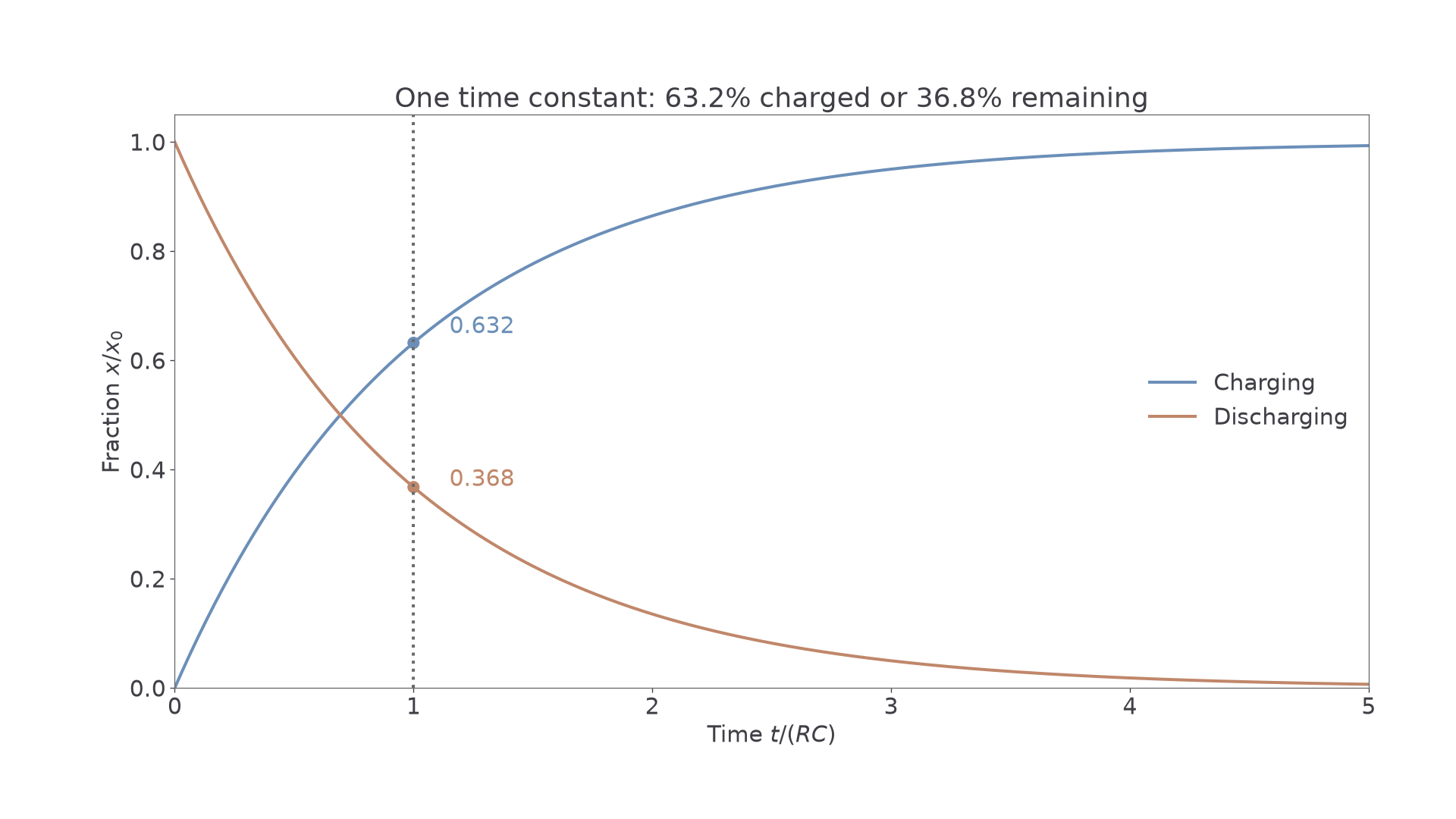
After one time constant, a discharging quantity has fallen to about 37% of its starting value. That wording matters: it has not "fallen by 37%". In the same time, a charging capacitor's p.d. or charge has risen to about 63% of its final value.
Worked example: a capacitor of capacitance discharges through a resistor from an initial p.d. of . Find the time for the p.d. to fall to .
First calculate the time constant:
Use the discharge equation:
Take natural logs:
The answer is sensible because is below 37% of , so the time should be a little more than one time constant.
Investigating charge and discharge
For PAG9-style work, the aim is usually to measure how , , or changes with time for a capacitor charging or discharging through a resistor.
A slow enough experiment can be done with a voltmeter and stopwatch:
- connect the voltmeter across the capacitor
- choose and so that is several seconds or longer
- charge the capacitor to a known initial p.d.
- move the switch to the discharge position and start timing
- record the p.d. at regular times until the p.d. is small
- repeat if needed, or recharge to the same initial p.d. before another run
For a fast circuit, a human reading a stopwatch and voltmeter is not good enough. Use a data logger with a voltage sensor across the capacitor, or an oscilloscope if the event is very fast. The sampling interval must be short compared with the time constant, otherwise the shape of the curve is poorly resolved.
The independent variable is time. The dependent variable is usually p.d. across the capacitor. Important control variables include the resistance, capacitance, supply p.d., temperature of the resistor if heating could matter, and the initial p.d. before each discharge.
Uncertainty and evaluation points are often where marks are won. A digital voltmeter has finite resolution; a stopwatch has reaction-time uncertainty; component values have tolerances; and very small p.d. readings near the end of a discharge can be noisy. A safer and cleaner method is to keep the supply below the capacitor's voltage rating, check polarity for electrolytic capacitors, and discharge larger capacitors through a resistor before handling or changing the circuit.
Continue this lesson.
You’re previewing NovaLearn without an account. Create a free account to read the rest.
Create free account