4.3.1 - Series, parallel and multi-source circuits
Circuit analysis is bookkeeping for charge and energy. In this lesson you will use Kirchhoff's laws to decide what must be the same, what must split, and how e.m.f.s and p.d.s balance in a loop. By the end, a mixed resistor network or a circuit with two sources should feel like a sequence of decisions rather than a guess.
Kirchhoff Laws as Conservation Rules
Kirchhoff's laws are not extra circuit equations to memorise separately from physics. They are conservation laws written in electrical language.
Kirchhoff's First Law
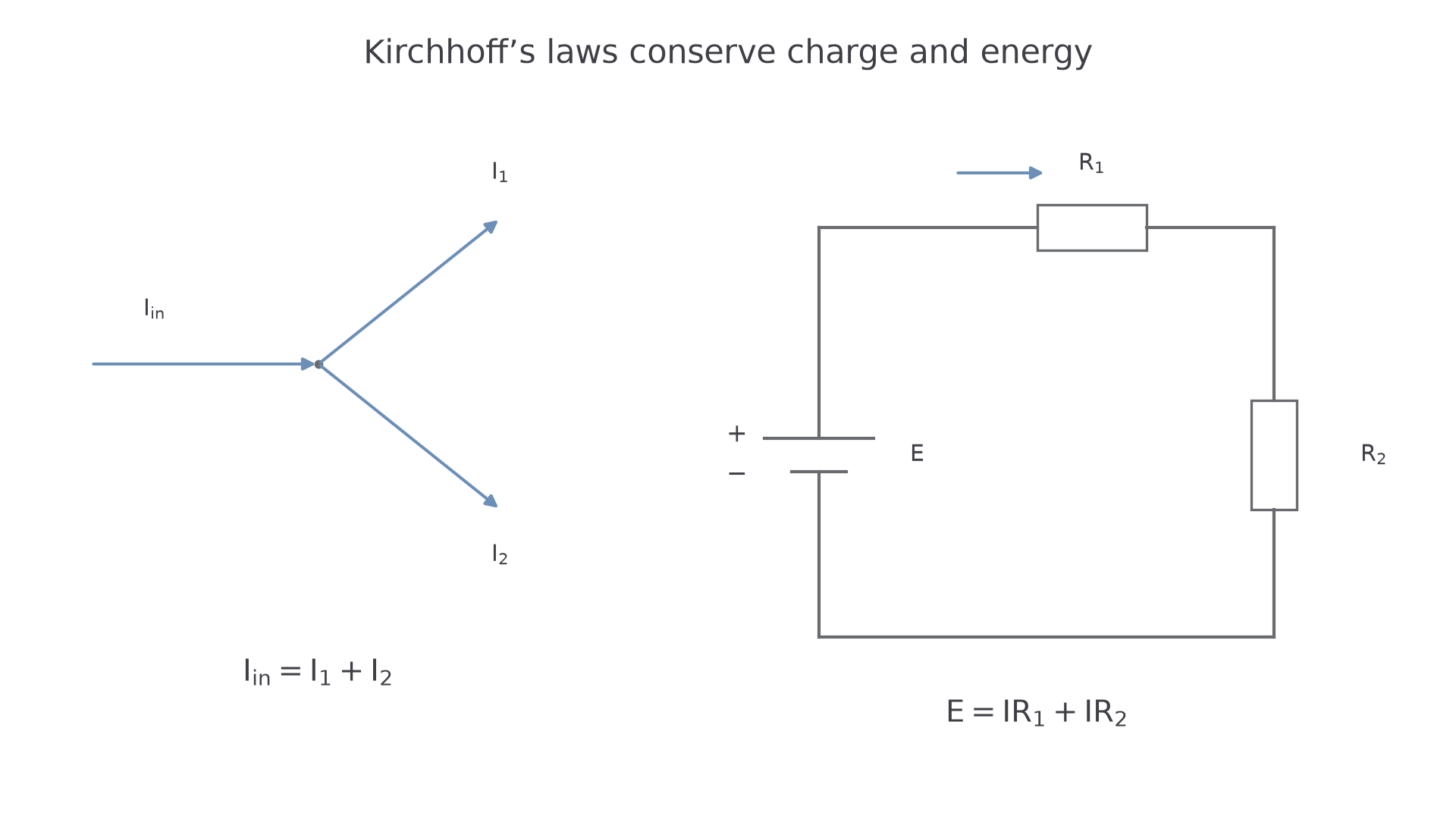
At any junction in an electrical circuit, the total current entering the junction is equal to the total current leaving the junction.
This is conservation of charge. Charge does not build up at an ordinary junction in a steady d.c. circuit, so every coulomb per second entering must leave.
Kirchhoff's Second Law
Around any closed loop in an electrical circuit, the sum of the e.m.f.s is equal to the sum of the potential differences across the components.
This is conservation of energy. A source transfers energy to each coulomb of charge; components transfer energy from each coulomb to the surroundings. If you return to the same point in the circuit, the net change in energy per unit charge is zero.
For calculations, choose directions for currents before you start. If the final value of a current is negative, the current actually flows in the opposite direction to your assumption. The negative sign is useful information, not a failed calculation.
Worked example: three wires meet at a junction. A current of enters the junction. Currents of and leave the junction.
Using Kirchhoff's first law:
So leaves through the third wire.
[DIAGRAM: asset_slug: 4_03_1_series_parallel_and_multi_source_circuits__diagram_01; description: Kirchhoff’s first law conserves charge at a junction and the second conserves energy around a loop.; caption: Kirchhoff’s laws express conservation of charge and energy.]
Series and Parallel Resistor Rules
Components are in series when they are connected in one path, so the same current passes through each component. Components are in parallel when they are connected between the same two nodes, so the same p.d. is across each branch.
Series Connection
Components are in series if there is no junction between them, so there is only one path for the current through those components.
In a series chain, each resistor transfers some energy from each coulomb of charge. The p.d.s add, so the resistances add.
Total Resistance in Series
Here is the equivalent resistance in ohms, . This relationship is in the OCR data booklet, but you must recognise when the components really are in series.
Parallel Connection
Components are in parallel if each component is connected across the same pair of nodes, so the same p.d. is across each branch.
In a parallel network, each extra branch gives charge another conducting route. The total current from the supply increases, so the equivalent resistance decreases.
Total Resistance in Parallel
For two resistors in parallel, the equivalent resistance is always less than the smaller resistor. That is a useful check on your calculation.
Worked example: find the total resistance of and connected in parallel.
The answer is below , so the size is physically sensible.
Misconception contrast: current is not used up by a resistor. In a series chain the same current is everywhere, but energy per coulomb is transferred in each component, so the p.d. changes from component to component.
Series means same current and added p.d.s. Parallel means same p.d. and split currents.
The rules follow directly from the conservation laws. In series, , so . In parallel, . Dividing by the common p.d. gives . This derivation also explains why an added branch reduces total resistance: at fixed p.d. it adds current.
Reducing Mixed Circuits
A mixed circuit contains some components in series and some in parallel. The safest method is to simplify one clear section at a time, replacing it with an equivalent resistance.
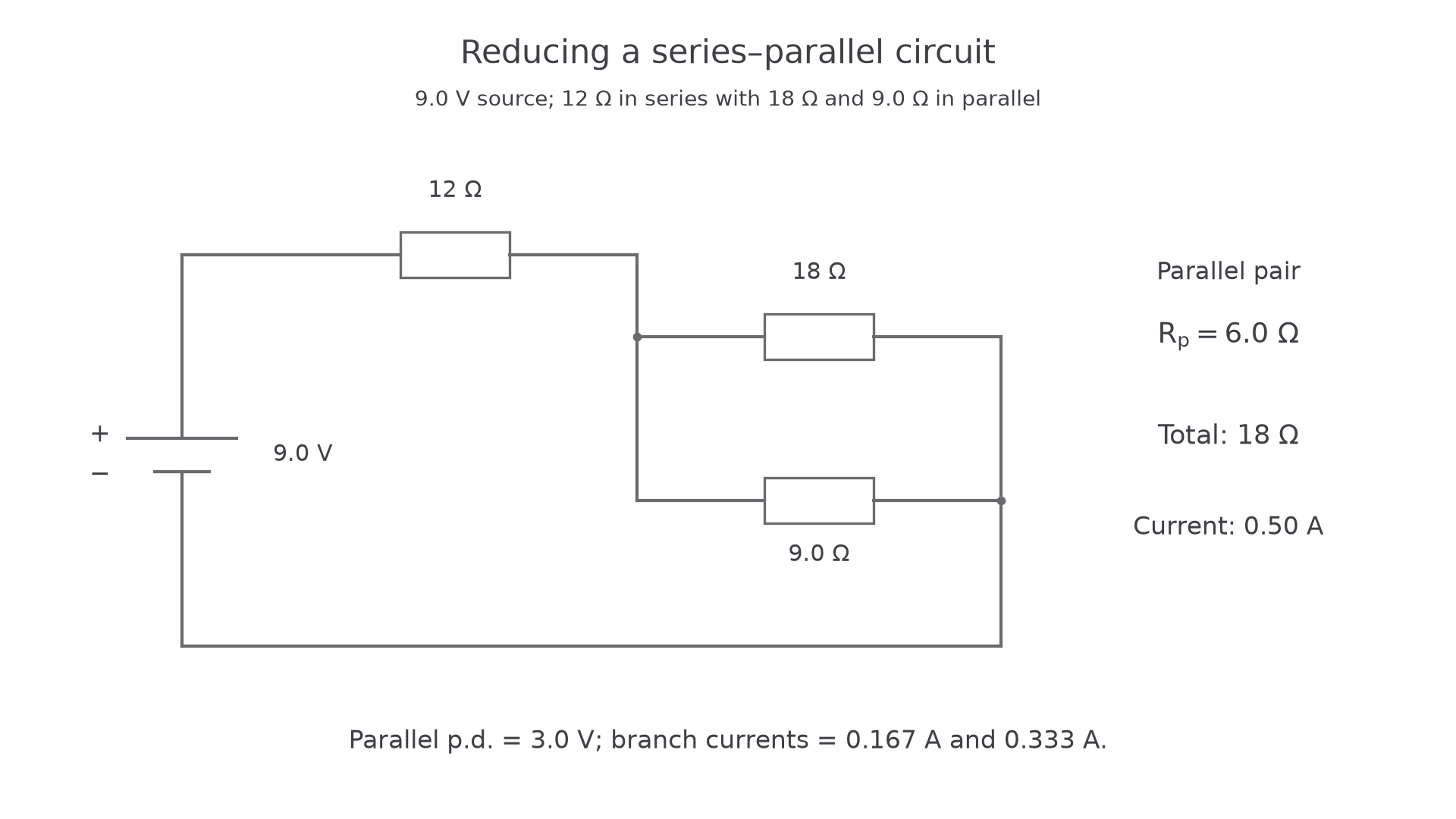
Worked example: a supply is connected to a resistor in series with a parallel pair of and resistors. Find the total current and the current in each parallel branch.
First reduce the parallel section:
Now add the series resistor:
Use for the whole circuit:
The resistor is in series with the supply, so it carries . Its p.d. is:
The remaining p.d. across the parallel section is:
Each parallel branch has across it:
The branch currents add back to , which checks Kirchhoff's first law.
If a circuit is not reducible by obvious series and parallel groups, use Kirchhoff's laws directly. OCR questions at this level usually make the reducible section identifiable, but the reason the reduction works is always Kirchhoff's first and second laws.
[DIAGRAM: asset_slug: 4_03_1_series_parallel_and_multi_source_circuits__diagram_02; description: A 12 Ω resistor in series with an 18 Ω and 9 Ω parallel pair.; caption: A 12 Ω resistor in series with an 18 Ω and 9 Ω parallel pair.]
Continue this lesson.
You’re previewing NovaLearn without an account. Create a free account to read the rest.
Create free account