4.3.3 - Potential dividers and sensors
Potential dividers turn a fixed input p.d. into a chosen output p.d. by sharing voltage between series components. In this lesson you will see why the sharing depends on resistance, how a potentiometer is just an adjustable divider, and how an LDR or thermistor converts a change in light or temperature into a changing voltage signal.
The Divider Idea
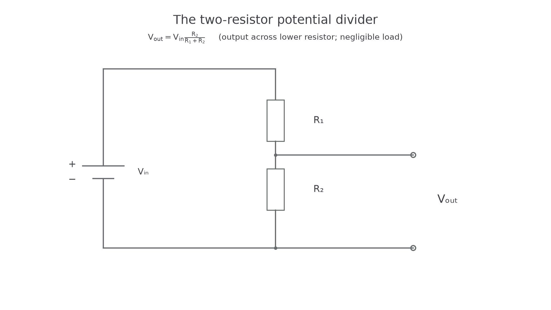
A potential divider is a series circuit connected across an input potential difference. The output p.d. is taken across one chosen component, often from the junction between two resistors to one end of the supply.
Potential Divider
A potential divider is a circuit in which two or more components in series share an input p.d., so that an output p.d. can be taken across part of the series chain.
The key point is that the two resistors are in series, so the same current passes through both. If the input p.d. is , then the total resistance is , so
The p.d. across is then . Substituting the expression for gives the standard potential-divider equation.
Potential Divider Output
Here is the p.d. across . If the output is taken across a different component, that component's resistance goes in the numerator.
Worked example: a supply is connected across and . The output is across .
That answer is sensible because is two thirds of the total resistance, so it gets two thirds of the input p.d. The common trap is to think the output must be "what is left over"; really, it is the p.d. across whichever component the output terminals are connected across.
The derivation assumes negligible current is drawn from the output. A connected load is in parallel with , reducing the effective lower resistance. For example, two resistors across give unloaded. A load across the lower resistor makes that arm , giving . A high-input-resistance meter avoids this loading error.
[DIAGRAM: asset_slug: 4_03_3_potential_dividers_and_sensors__diagram_01; description: The unloaded output across the lower resistor is its fraction of the input p.d.; caption: An unloaded divider shares the supply p.d. between two resistors.]
Ratios and Potentiometers
For any two series resistors carrying the same current, the p.d. across each resistor is proportional to its resistance:
Divider Ratio
This is often the quickest route when you know two p.d.s or want to find an unknown resistance. It is the same physics as the equation: the larger resistance has the larger share of the input p.d.
Worked example: a divider is supplied by . The output across the lower resistor must be , and the upper resistor is . The upper resistor therefore has across it.
So . The resistance ratio is , matching the voltage ratio .
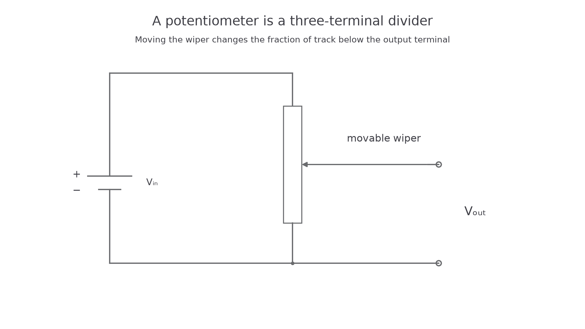
A potentiometer is a potential divider with a sliding contact on a resistive track. The track is connected across the supply; the slider selects how much of the track lies above and below the output point. Moving the slider changes the two resistances, so the output p.d. can be varied smoothly.
If the output device has a very high resistance, almost no current leaves through the output terminal. Then the track still behaves like a simple series divider. If the output device draws a significant current, the divider is loaded and the simple equation no longer gives the exact output p.d.; for this course, use a high-resistance voltmeter or input when measuring .
[DIAGRAM: asset_slug: 4_03_3_potential_dividers_and_sensors__diagram_02; description: A potentiometer wiper selects a variable fraction of the supply p.d.; caption: A potentiometer wiper selects a fraction of the supply p.d.]
Sensors in Dividers
An LDR and a thermistor are useful in potential dividers because their resistance changes when the environment changes. The divider turns that resistance change into a changing output p.d.
Light-Dependent Resistor
An LDR is a resistor whose resistance decreases when the intensity of incident light increases.
For the thermistors normally used in OCR sensor circuits, the thermistor is an NTC thermistor.
NTC Thermistor
An NTC thermistor is a temperature-dependent resistor whose resistance decreases as its temperature increases.
The direction of the voltage change depends on where the sensor is placed and where the output is taken. If the output is across a sensor in the lower arm, then a decrease in the sensor resistance makes decrease. If the same sensor is placed in the upper arm and the output is across a fixed lower resistor, the output increases when the sensor resistance decreases.
Here is a numerical version of the idea. A supply is connected across a fixed upper resistor and an LDR as the lower resistor. The output is across the LDR.
In dim light, suppose :
In bright light, suppose :
So this arrangement gives a high output in dim light and a low output in bright light. If a design needs the output to rise in bright light, put the LDR in the upper arm and take the output across the lower fixed resistor.
Continue this lesson.
You’re previewing NovaLearn without an account. Create a free account to read the rest.
Create free account