4.4.3(f)-(g) - Young's double slit and diffraction gratings
Thin slits can turn a beam of light into a measurement tool. In this lesson you will see why Young's double-slit experiment was classical evidence for the wave nature of light, how to use the fringe-spacing equation, and how a diffraction grating gives sharper angular maxima for wavelength measurements. The practical thread is the same throughout: measure a distance or angle carefully, convert it into a wavelength, and keep the geometry honest.
Young's experiment as wave evidence
Young's double-slit experiment uses a common monochromatic light source illuminating two very narrow, close slits. The two slits then act as coherent sources of waves, so the waves from the two slits overlap on a screen. Instead of simply making two bright patches, the screen shows a pattern of bright and dark fringes.
The bright fringes are positions where the two waves arrive in phase and interfere constructively. The dark fringes are positions where the waves arrive in antiphase and interfere destructively. That repeated bright-dark-bright pattern was important historically because it is exactly the kind of behaviour expected from waves that superpose.
OCR expects you to know the significance of this experiment: Young's double-slit experiment gave a classical confirmation of the wave nature of light. "Classical" matters here. This is not yet the quantum double-slit story about single photons; it is the A-level wave-optics evidence that visible light can diffract, superpose and interfere.
The historical argument is often framed as Newton's particle-like model of light against Huygens' wave model. Young's result supported the wave model because a stable interference pattern is naturally explained by path difference and phase, not by two independent streams of particles making two simple bright regions.
The double-slit fringe equation
The useful measurement in a Young double-slit experiment is the fringe spacing.
Fringe spacing
The fringe spacing is the distance between the centres of adjacent bright fringes, or adjacent dark fringes, on the screen.
Use these symbols:
- : separation between the centres of the two slits, in m
- : distance from the double slit to the screen, in m
- : fringe spacing on the screen, in m
- : wavelength of the light, in m
For the distant-screen, near-axis fringes used here, the first bright-fringe angle is small. The small-angle approximation is:
The distant-screen condition makes the two paths nearly parallel. Use low-order fringes close to the central axis, with , so their angle is small and . The slit-separation condition alone does not guarantee small angles for every point on the screen.
For adjacent bright fringes, the path difference changes by one wavelength. The geometry gives the standard relationship:
For the first bright fringe, the path difference is . The screen triangle gives . For a small angle measured in radians, , so . Adjacent near-axis bright fringes are separated by the same . This derivation identifies exactly where the approximation enters.
Young double-slit fringe spacing
Equivalently,
This form is often more useful for predicting what happens. A longer wavelength gives a larger fringe spacing. A larger screen distance gives a larger fringe spacing. A larger slit separation makes the fringes closer together.
Worked example: predicting the fringe spacing
A red laser of wavelength passes through a double slit with slit separation . The screen is from the slits. Calculate the fringe spacing.
First convert the slit separation:
Use :
So the bright fringes are about apart.
[DIAGRAM: asset_slug: 4_04_3b_youngs_double_slit_and_diffraction_gratings__diagram_01; caption: Slit separation, screen distance and adjacent fringe spacing are separate measurements in the double-slit experiment.; description: The slit separation a, screen distance D and adjacent fringe spacing x are distinct measurements. The approximation lambda = ax/D uses distant-screen near-axis fringes.]
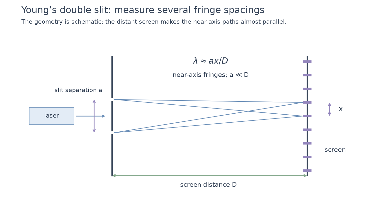
Determining wavelength with double slits
A double-slit wavelength experiment is simple in principle, but the measurements need care because visible-light wavelengths are tiny. A typical method uses a low-power laser, a double slit with known slit separation , a screen or paper scale, and a metre ruler to measure .
The method is:
- Direct the laser normally at the double slit and place the screen several metres away if practical.
- Measure , the distance from the double slit to the screen.
- Measure the distance across several bright fringe spacings, centre-to-centre.
- Divide by the number of spacings to find the mean fringe spacing .
- Calculate .
Measuring several fringe spacings is much better than measuring one small spacing. For example, if the distance across ten spacings is , then
That reduces the percentage uncertainty in , because the same ruler uncertainty is spread over a larger measured distance.
Good practical technique also includes alignment and safety. Keep the laser fixed and low power, keep the beam away from eye level, and never look into the direct beam or reflected beam. Make the screen perpendicular to the beam and measure to the centres of fringes, not their edges. If the pattern is faint, reduce room light rather than increasing risk with an unsuitable laser.
You can also repeat the experiment for different screen distances . Since , a graph of against should be a straight line through the origin with gradient . Then . This graph method uses many readings instead of relying on one pair of measurements.
Fit the measured trend and check the intercept against zero; do not force an experimental line through the origin if an offset is indicated. Measuring between the first and eleventh bright fringes spans ten spacings, not eleven.
Continue this lesson.
You’re previewing NovaLearn without an account. Create a free account to read the rest.
Create free account