FR3, FG13, HR3, HG15 - Scale drawings and bearings
Learn to turn map lengths into real distances, construct a consistent scale drawing, and describe directions using three-figure bearings. FR3 and HR3 supply the scale-factor reasoning; FG13 and HG15 combine accurate measurement with maps, angles and bearings.
Scale drawings
How can a route several kilometres long fit on a page without changing its shape? A scale drawing uses the same length multiplier everywhere, while keeping the angles unchanged.
Scale
A scale means one unit on the drawing represents of the same unit in reality. At , represents .
Convert units before using a ratio scale. Going from drawing to reality multiplies lengths by ; going back divides by . A verbal scale such as “ represents ” says the same thing in different units.
Worked example 1: drawing to reality
Question. A map has scale . A straight path measures on it. Find the actual distance in kilometres.
Plan. Multiply by the scale factor in centimetres, then convert to kilometres.
Answer. .
Check. Each map centimetre represents , and .
Reverse the question while keeping the scale and distance unchanged. This time division finds the length to draw.
Worked example 2: reality to drawing
Question. At scale , how long should a straight path be drawn?
Plan. Convert the actual distance to centimetres, then divide by .
Answer. Draw .
Check. Reversing the conversion gives , the required distance.
For a construction on paper, calculate every drawing length first. For example, an by rectangular park at becomes an by rectangle. Use a ruler from its zero mark, draw the given right angles, and join the vertices accurately. Do not use one scale horizontally and another vertically.
On a screen, resizing an image changes its physical centimetres. Use a labelled scale bar or supplied measurements rather than treating a centimetre on your screen as a printed map centimetre.
Watch out
does not mean . The ratio compares the same units; convert afterwards.
Find a fresh construction length.
Measuring directions
A bearing describes a direction from a specified starting point, measured clockwise from north at that point.
Three-figure bearing
A bearing is the clockwise angle from north, written with three digits. North is , east , south and west . For instance, east of north has bearing .
To measure a bearing on paper, draw or locate the north line through the starting point. Put the protractor's centre at that point and its zero along north. Read clockwise towards the destination, using the appropriate scale. For an angle greater than , measure the remaining smaller angle carefully and subtract it from . Do not begin at the destination or measure from an eastward horizontal line.
[DIAGRAM: asset_name: Bearings on either side of north; asset_slug: bearings-from-north; caption: The same small angle from north can give different clockwise bearings.; description: Two exact compass diagrams show rays 40 degrees east of north and 40 degrees west of north, labelled bearings 040 degrees and 320 degrees respectively. North, east, south and west are marked, and the clockwise bearing sweeps begin at north.]
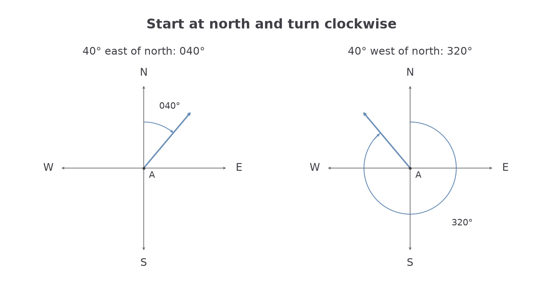
Worked example 3: east of north
Question. From , point is east of north. Write the bearing of from .
Plan. Begin at north through and measure clockwise to .
The clockwise angle is already . Write it with three digits.
Answer. .
Check. The direction lies between north and east , as does.
Move the direction to the other side of north, keeping the small angle . A bearing still travels clockwise.
Worked example 4: west of north
Question. From , point is west of north. Write the bearing of from .
Plan. Subtract the small anticlockwise angle from a complete turn.
Answer. .
Check. Northwest directions have bearings between and , so is in the correct quadrant.
Continue this lesson.
You’re previewing NovaLearn without an account. Create a free account to read the rest.
Create free account