Physics 4.7, 4.17 - Measuring wave speed
Measure sound in air, ripples in water and waves in a metal rod. Choose instruments that resolve the required distances and times, then use repeats and comparisons to judge how trustworthy the measurements are.
Quantities and measurement routes
A wave transfers energy through a system. Wave speed is the distance travelled by a recognisable part of the wave pattern per unit time; it is not the speed of a parcel of water or air being carried from source to detector. For a water wave, a crest or straight wavefront can be followed. For sound, a short pulse can be detected electronically even though it cannot be seen.
Frequency, , is the number of complete cycles passing a point each second, measured in hertz (). Wavelength, , is the shortest distance between two points in the same stage of a wave, such as one crest to the next crest, measured in metres (). Wave speed, , is measured in metres per second ().
Two routes to wave speed
Direct timing:
- is the distance travelled by the wave pattern, in metres.
- is the travel time, in seconds.
Frequency and wavelength:
- is frequency, in hertz.
- is wavelength, in metres.
The direct route is useful when one crest or pulse can be identified and its travel time is resolvable. The second route is useful when frequency and wavelength can be measured more reliably than a very short transit time. Two supporting measurements improve both routes:
- If crests pass a fixed point in time , then . Counting over several seconds reduces the percentage effect of starting and stopping the timer late.
- If a measured distance spans complete crest-to-crest gaps, then . Measuring five or more wavelengths reduces the percentage effect of ruler resolution.
Convert every length to metres before substitution. Keep unrounded values through the calculation, then report a sensible number of significant figures with the unit.
Measuring sound speed in air
The aim is to measure the time taken by the same sound pulse to travel a known distance through air. Human reaction time is much longer than the few milliseconds involved, so two microphones and a data logger replace a handheld stopwatch.
Apparatus and arrangement
Use two microphones connected to separate data-logger channels, a metre rule or tape measure, connecting leads, two wooden blocks to make a sharp pulse, and a thermometer if results from different times are to be compared. Put the microphones in one straight line, facing the same way. Measure the separation between the corresponding sensing points of the microphones, and make the sound just before microphone 1 so that the pulse reaches microphone 1 and then microphone 2.
Reproducible method
- Set the logger to a sampling rate fast enough to distinguish times separated by less than a millisecond, then check that both microphone traces respond to one tap.
- Place the microphones apart and measure the separation from sensing point to sensing point, not from the edges of their cases.
- Tap the blocks together once close to microphone 1. On the two traces, identify the leading edge of the same pulse and measure the delay between detections.
- Calculate .
- Repeat at least three times. Recheck any trace that contains a second pulse or a strong echo; do not remove a value merely because it differs.
- Repeat for larger separations, for example , , and , if the room and logger allow. Calculate a speed for every valid trial and a mean from the repeat speeds.
The microphone separation is the deliberately changed variable used to test whether the method gives a consistent speed. The measured time delay and calculated speed are the dependent outcomes. Keep the microphone type and alignment, sound source, source position, logger settings, room and temperature as constant as possible. A larger separation produces a larger delay, so one sampling interval or one cursor-placement error is a smaller percentage of the result.
Keep leads tidy to prevent trips. Make a moderate pulse rather than repeated very loud sounds, and keep fingers clear when tapping the blocks. Reflections from nearby walls can create extra peaks; use the first arrival of the same pulse at each microphone and work away from large reflecting surfaces where possible.
Worked example: a time-of-flight measurement
Two microphones are separated by . The second trace begins after the first.
- The given quantities are already in metres and seconds: , .
- Select the direct route: .
- Substitute: .
- Calculate without early rounding: .
- Report to 3 significant figures: .
The value is physically plausible for sound in room-temperature air. An answer of only a few metres per second would signal that milliseconds had probably been treated as seconds or that the wrong time interval had been used.
An echo method is a valid lower-precision alternative: stand a measured distance from a large wall, measure the delay between a sharp sound and its echo electronically, and use the full sound path . Using alone would omit the return journey.
Fluid method: waves on water
Water is the fluid in this core practical. A ripple tank makes the wavefronts slow and visible enough to measure frequency, wavelength and speed separately, then compare two routes to the speed of the same wave train.
Apparatus and arrangement
Use a level ripple tank with shallow water and absorbing beaches, a straight dipper driven by a low-voltage vibrator, a lamp or built-in illumination, a ruler, a white screen or scale visible with the waves, a stopwatch, and a camera capable of a sharp still image or video. The straight dipper should produce broad parallel wavefronts across the tank. Keep electrical supplies on the bench and away from water.
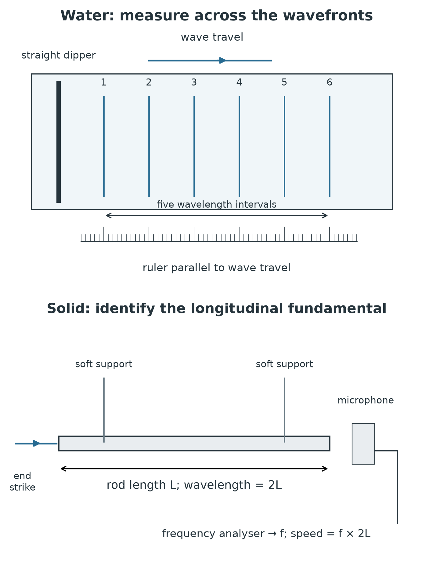
The rod illustration is schematic: loose soft supports keep the ends free. Identify the longitudinal fundamental before using the length relationship.
[DIAGRAM: asset_slug: phy_c_wave_measurements_verified; description: Six water wavefronts span five wavelength gaps; ruler parallel to travel. Soft-supported rod receives end-on strike; microphone records identified longitudinal fundamental.]
Reproducible method
- Level the tank and add a uniform shallow layer of water. Fit beaches at the far sides to reduce reflected waves that could overlap the outgoing wavefronts.
- Put the straight dipper near one end and run it slowly enough to give distinct, evenly spaced wavefronts. Wait for a steady pattern before measuring.
- Measure frequency: choose a fixed point and count complete crests passing it in . Repeat the count and calculate for each trial.
- Measure wavelength: take a sharp photograph or pause a video with a ruler in the same measurement plane. Measure a distance across at least five complete crest-to-crest gaps and calculate .
- Measure speed directly: mark two points a known distance apart along the direction of travel. Use video frames or a stopwatch to measure the time for one identifiable crest to travel between them, then calculate .
- Repeat each measurement at least three times without changing the water depth or vibrator setting. Record raw counts, distances and times before calculating means.
- Calculate a second speed for the same wave train using . Compare this with the mean direct speed; agreement supports the equipment's suitability but does not by itself prove either value is accurate.
This is an equipment-comparison investigation, not a causal investigation that requires a continuous independent variable. The categorical comparison is the measurement route, or ; the outcome is the calculated speed and its repeat spread. Control water depth, tank level, vibrator setting, measurement region and scale position so both routes refer to the same wave train. Use the longest clear timing distance and several wavelengths rather than trying to make tiny single-interval measurements.
A suitable raw-results table keeps observations visible:
| Trial | Crests counted | Count time / s | Frequency / Hz | Distance across wavelengths / m | Wavelength / m | Crest distance / m | Crest time / s | Direct speed / | |
|---|---|---|---|---|---|---|---|---|---|
| 1 | |||||||||
| 2 | |||||||||
| 3 |
Worked example: two speed routes
In one stable pattern, 20 crests pass a fixed point in . A photograph shows that five complete wavelengths span . A crest also travels in .
Continue this lesson.
You’re previewing NovaLearn without an account. Create a free account to read the rest.
Create free account