Physics 2.19 - Force, mass and acceleration practical
Investigate how adding mass to a trolley changes acceleration. Use light gates, keep the external drive approximately constant, and distinguish the trolley from the whole moving system when interpreting forces.
Force, mass and acceleration practical
The purpose is to investigate how the acceleration of a trolley changes when the total
moving mass changes while the external driving force is kept as constant as possible. A fixed mass
hanging from a string provides the pull; known masses are added to the trolley. Two light
gates measure velocity at two positions and the time between those measurements.
[DIAGRAM: asset_name: Trolley force practical; asset_slug: physics_2_14_2_19_newton_laws_weight_and_force_practical__diagram_01; description: A perspective schematic of a trolley, added masses and interrupt card passing two light gates, pulled by a fixed hanger over a pulley. The release end is raised slightly and the slope is checked using the detached trolley moving slowly at constant velocity. A catch box protects the falling hanger.]
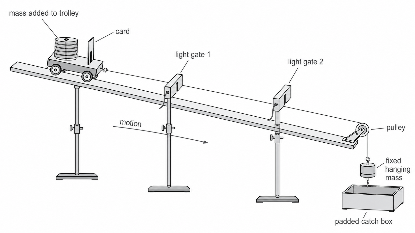
Apparatus and arrangement
Use a dynamics trolley, a shallow ramp with low-friction trolley wheels, stacking masses, balance,
card of measured length, two light gates with clamps and datalogger, string, clamped pulley,
fixed mass hanger and a padded catch box. The string must remain aligned with the trolley.
The trolley's card must pass cleanly through both gates before the trolley reaches the pulley
or the hanger reaches the catch box.
Check that the trolley and pulley move freely. Raise the release end very slightly. With the string detached, give the trolley a gentle push and adjust the slope until it moves slowly at approximately constant velocity. This compensates for rolling friction more appropriately than waiting for a stationary trolley merely to start moving. Keep this small ramp angle fixed during the investigation and check that the compensation remains reasonable with the chosen added masses. For the whole moving system (trolley, added masses and hanger), string tension is internal: the hanger's weight, , drives the motion. The trolley's small downslope weight component approximately balances its rolling friction. Residual imbalance and pulley resistance mean that is only an approximation to the net drive, not an exact resultant.
For the trolley alone, the pull is string tension. Because the hanger accelerates downward, tension is less than its weight even in an ideal light-string model. An in-line force sensor measures that tension; its reading must be used with the trolley's mass, with trolley friction also considered. Do not combine trolley tension with total system mass.
Variables
| Role | Quantity and unit | How it is handled |
|---|---|---|
| Independent | total moving mass, kg | add known masses to the trolley; include trolley, added masses and fixed hanger in the system total |
| Dependent | mean acceleration between the gates, | calculate from , and the time between their measurements |
| Controlled | driving force | keep the hanging mass and local unchanged |
| Controlled | ramp and timing geometry | keep track angle, gate positions, card length and release point unchanged |
| Controlled | moving apparatus | use the same trolley, string, pulley and clean track; release without a push |
Reproducible method
- Clamp the pulley and both light gates securely. Put the padded catch box beneath the
hanger and check that the runway cannot slip. - Set the shallow friction-compensation slope as described, then leave its angle fixed. Attach the measured card to
the trolley so it remains upright and passes through both gates. - Measure and record the masses of the trolley, each added mass and the fixed hanger in
kilograms. Measure the hanger’s stationary weight with a zeroed newton meter; compare the newton reading with . This measures the external drive estimate. If available, use a light in-line force sensor to record the string tension during each run as a separate trolley-only force measurement. - Attach the trolley to the fixed hanger using the string over the pulley. Set the string
length and gate positions so the hanger remains clear of the catch box until the card has
completely passed the second gate. - Start with no added trolley mass. Release the trolley from the marked position without a
push. Record the first-gate velocity , second-gate velocity , and time
between the velocity measurements. - Repeat at least three times from the same position. Do not delete an unexpected result
automatically: check for a release, gate or collision fault, then repeat and record why a
result is treated as anomalous. - Add the next trolley mass while keeping the hanger unchanged. A useful range is at least
five safe, evenly spaced added masses, for example 0, 0.10, 0.20, 0.30 and , if the
equipment can still travel safely through both gates. - Calculate acceleration for every run, then calculate the mean acceleration for each total
moving mass.
Risks and controls
- Falling hanger or masses: they could strike feet or damage the floor. Use small masses,
place a padded catch box below them, keep feet clear and retrieve masses only when still. - Moving trolley: it could hit the pulley or leave the ramp. Keep the travel path clear,
choose a safe pull and arrange the second gate so the trolley can be stopped after passing
it. - Unstable ramp, pulley or gate stands: equipment could slip or fall. Clamp the pulley and
gates, use a stable low runway, and check supports before release.
Processing and evaluating results
The light gates give velocities at two known stages of the motion. The relevant time is the
time between those velocity measurements, not either card-blocking time on its own. At each
gate, the datalogger divides the measured card length by the time for which the card blocks
the beam to obtain the local velocity.
Mean acceleration between the gates
Here is the first velocity in , is the second velocity in , and is
the time between the velocity measurements in s.
Continue this lesson.
You’re previewing NovaLearn without an account. Create a free account to read the rest.
Create free account