Physics 10.21 - Investigating component resistance
A useful investigation changes one relevant quantity and measures the response of the component. Design circuits for lamps and diodes, then adapt the method to investigate how temperature and light intensity affect resistance.
Equation support is provided for GCSE Combined Science Physics examinations in 2025–2027. Practise choosing, interpreting and rearranging the supplied relationships; these activities do not assume unaided equation memorisation.
Designing and using the test circuit
The same basic low-voltage d.c. test circuit can explore a lamp, diode, thermistor or LDR. Its job is to produce matched measurements of the current through the component and the p.d. across it.
[DIAGRAM: asset_slug: phy_f_component_investigation; description: Current-measuring series loop with a voltmeter across only the component under test.]
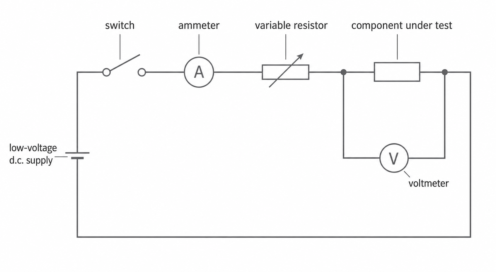
The circuit has five important design choices:
- The ammeter is in series so it measures the current through the tested component.
- The voltmeter is in parallel across only the tested component so it measures that component's p.d.
- A variable resistor is in series. It changes the circuit current and protects low-resistance components by limiting current.
- A low-voltage d.c. supply lets the p.d. be changed safely. Begin at a low setting and choose meter ranges that will not be exceeded.
- A switch lets the circuit be disconnected between readings, reducing unnecessary heating.
For a diode, retain a suitable fixed current-limiting resistor as well as any variable control if the variable resistor can reach zero. Start with the largest variable resistance and lowest supply setting. A small increase in forward p.d. can produce a large current, so never exceed the diode’s rated current.
Investigate lamps and diodes
Keep the component, meter connections and ranges the same during a run. Vary the potential difference using the low-voltage supply or variable resistor. At each setting record the p.d. across the component in volts and the current through it in amperes. Use several well-spaced settings, with closer spacing where current changes rapidly.
For a filament lamp, allow the reading and brightness to settle at each setting. Its working temperature changes as p.d. increases; this is the reason its resistance changes. Do not claim to control the filament to one temperature during its characteristic investigation. Switch off before reversing the supply and collect negative-polarity readings if a complete characteristic is required. Allow the lamp to cool before handling.
For a diode, start at the lowest supply setting and retain the series current limiter. Take readings in the forward direction, watching the current carefully near the steep-rise region. Switch off, reverse the diode or supply connections, then repeat within its safe reverse-voltage range. Never increase reverse voltage until breakdown. At GCSE, reverse current is approximately zero over the range used.
Continue this lesson.
You’re previewing NovaLearn without an account. Create a free account to read the rest.
Create free account