Physics 10.17 - Core practical circuit measurements
Build a resistor and filament-lamp test circuit, record paired current and potential-difference readings, and use them to calculate resistance. Then compare the same filament lamps in series and parallel using measured currents and potential differences.
Equation support is provided for GCSE Combined Science Physics examinations in 2025–2027. Practise choosing, interpreting and rearranging the supplied relationships; these activities do not assume unaided equation memorisation.
Build and check the measurement circuit
Core practical 10.17 has two linked investigations. First use a resistor, then a filament lamp, to measure current at different potential differences. Next compare filament lamps in series and parallel. Repeat the circuit-layout comparison using fixed resistors as well, as specified in 10.17(b).
[DIAGRAM: asset_slug: phy_f_practical_circuits; description: Component I–V test loop, series filament lamps, and parallel filament lamps with total and branch current meters.]
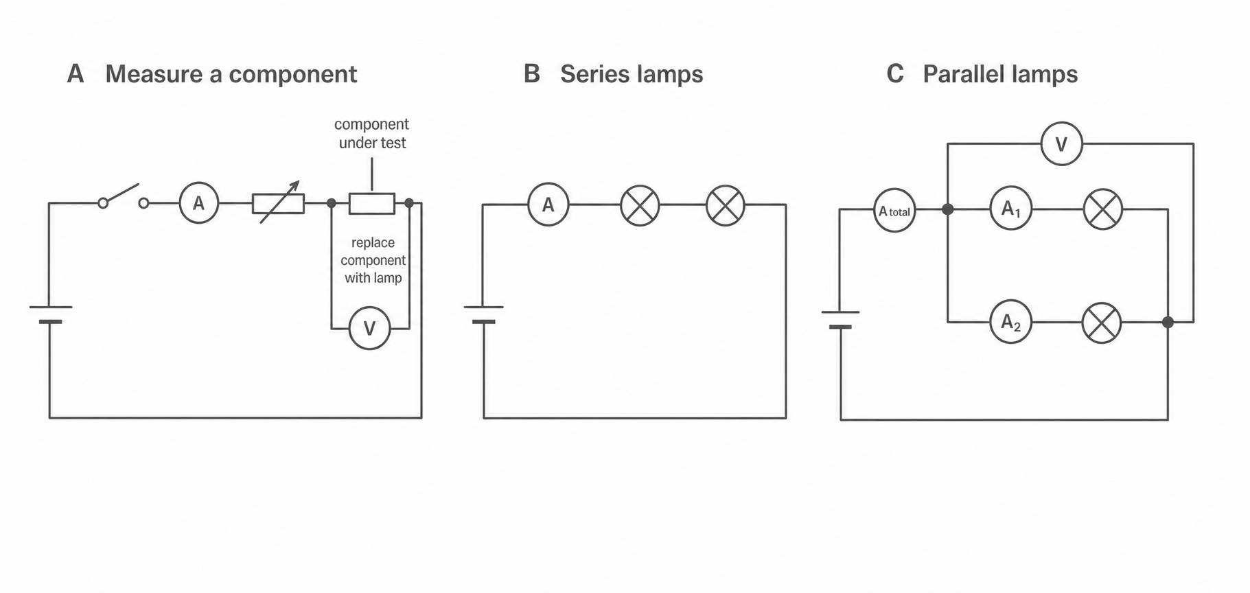
In Panel A, the ammeter, variable resistor and tested component are in series. The voltmeter connects across only the tested component. The low resistance of the ammeter lets the circuit current pass through it; the voltmeter has a high resistance so very little current enters its branch. Never put an ammeter directly across the supply.
Use a suitable low-voltage d.c. supply and keep the switch open while building or changing connections. Start at zero supply voltage or maximum variable resistance. Check the component rating, meter ranges and d.c. polarity before switching on. Panels B and C show the connections being compared; retain a switch in the supply route in the real circuits. Take voltage measurements across each lamp as described below, even where a meter is omitted from the simplified series diagram.
Core practical: measuring V, I and R
The first purpose of core practical 10.17 is to investigate the relationship between potential difference, current and resistance for a fixed resistor and a filament lamp.
Apparatus and variables
Use a suitable low-voltage d.c. supply, switch, ammeter, voltmeter, variable resistor, fixed resistor, filament lamp in a holder and connecting leads.
| Role | Quantity | How it is handled |
|---|---|---|
| Independent variable | Potential difference across the tested component () | Change it in regular safe steps using the supply or variable resistor |
| Dependent measurement | Current through the tested component () | Read the series ammeter at every setting |
| Calculated dependent quantity | Resistance () | Calculate for each pair of readings |
| Controls for a fair comparison | Component identity, connections and meter ranges | Use the same tested component during one run and the same procedure for both component types |
| Heating control for the fixed resistor | Component temperature as far as practicable | Use modest currents, take readings promptly, open the switch between readings and allow cooling before repeats |
Changing temperature is part of what happens when a filament lamp operates, so do not claim that its temperature remains constant. Instead, use the same lamp and take each reading consistently after the display has settled.
Method
- With the switch open, construct the component test circuit in Panel A: supply, switch, ammeter, variable resistor and fixed resistor in series, with the voltmeter across the fixed resistor.
- Set the supply to zero or the variable resistor to maximum resistance. Select suitable d.c. meter ranges and have the circuit checked.
- Close the switch. Adjust the control until the voltmeter shows the first chosen potential difference, then record the potential difference and current. For the fixed resistor, open the switch promptly after the readings to limit heating.
- Take at least six well-spaced pairs of readings across the component's safe operating range. Use regular intervals where the apparatus permits.
- Repeat each setting at least twice more. If one reading is inconsistent, check the connections and repeat it rather than deleting it without a reason. Calculate a mean current for each potential difference.
- Return the supply to zero, open the switch and replace the fixed resistor with the filament lamp. Repeat the same sequence without exceeding the lamp’s rating. For each lamp setting, allow the brightness and meter readings to settle before recording; its changing working temperature is part of the investigation. Switch off between sets and allow cooling before handling. If both polarities are investigated, switch off before reversing the supply and repeat the readings with the signs recorded.
Record raw measurements before calculating:
| Component | Potential difference / V | Current trial 1 / A | Current trial 2 / A | Current trial 3 / A | Mean current / A | / Ω |
|---|---|---|---|---|---|---|
| Fixed resistor or lamp |
Processing and conclusions
Plot mean current, (), on the vertical axis against potential difference, (), on the horizontal axis. Use a sensible linear scale, plot every mean and draw an appropriate best-fit line or smooth curve rather than joining each point dot-to-dot.
Calculate resistance at several readings using . For example, a reading of and gives:
This is a ratio at that reading. Do not automatically call the gradient of any current-potential-difference graph "the resistance". Typical fixed-resistor data give an approximately constant over the tested range; filament-lamp data may give different values at different readings. Conclusions must be based on the measured pattern, not on forcing both components to behave identically.
Continue this lesson.
You’re previewing NovaLearn without an account. Create a free account to read the rest.
Create free account