Physics 10.18 - 10.20 - Component characteristics
A fixed resistor, filament lamp and diode respond differently as the potential difference changes. Read their characteristic graphs, calculate resistance at a point, and explain how light and temperature change two useful sensors.
Equation support is provided for GCSE Combined Science Physics examinations in 2025–2027. Practise choosing, interpreting and rearranging the supplied relationships; these activities do not assume unaided equation memorisation.
Reading current-potential difference characteristics
A current-potential difference characteristic, often shortened to an I-V characteristic, shows how the current through one component changes as the potential difference across that component changes.
- Potential difference, , is plotted on the horizontal axis.
- Current, , is plotted on the vertical axis.
- Positive and negative values show opposite directions of potential difference and current. A negative current is not “less current”; it is current in the opposite direction.
Resistance at a point
, so
is in volts (V), is in amperes (A), and is in ohms (Ω).
The resistance at a non-zero point on an I-V graph comes from that point's ratio . Do not calculate resistance at the origin: is undefined. Also, do not call resistance “the gradient” of any curved I-V graph. With these axes, the gradient of a straight fixed-resistor line is , which is .
Worked example
A filament lamp has these two readings:
| Potential difference, | Current, |
|---|---|
Solution
At :
At :
The potential difference is four times larger while the current is only twice as large. The calculated resistance has increased from to , which is the expected behaviour of a filament lamp as it becomes hotter.
Three component characteristics
[DIAGRAM: asset_name: Physics 10.18-10.21 - Component characteristics and circuit design - diagram 01; asset_slug: physics_10_18_10_21_component_characteristics_and_circuit_design__diagram_01; recommended_method: matplotlib; description: Three aligned monochrome illustrative I-V plots with potential difference V on each horizontal axis and current I on each vertical axis: a straight fixed-resistor line through the origin, a symmetric filament-lamp curve that becomes less steep as the magnitude of potential difference increases, and a diode curve with approximately zero reverse current and a steep forward rise after a threshold region. Direct panel titles, no numerical scale, no reverse-breakdown branch, and a note that curves are illustrative and not to scale.]
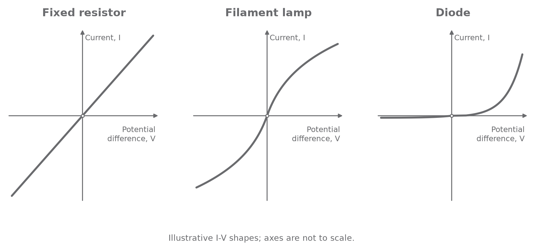
Fixed resistor
For a fixed resistor kept at constant temperature, current is directly proportional to potential difference. Doubling the p.d. doubles the current, so stays constant. Its I-V characteristic is a straight line through the origin. Reversing the p.d. reverses the current, giving the same pattern in the opposite quadrant.
For two straight fixed-resistor I-V lines, the steeper line has the smaller resistance because its gradient is . This shortcut is not valid for a curved component characteristic.
Continue this lesson.
You’re previewing NovaLearn without an account. Create a free account to read the rest.
Create free account