5.9 - Refraction in glass core practical
Trace light through a rectangular glass block, measure angles from the normal, and evaluate the evidence and uncertainty in a refraction investigation.
What refraction shows
Place a rectangular glass block in the path of a narrow beam of light. The beam changes direction as it enters the glass, travels in a straight line inside the uniform glass, then changes direction again as it leaves. This change of direction at a boundary is refraction.
A drawn ray is a model: its line shows the direction in which light travels and its arrowhead shows the direction of energy transfer. It is not the complete electromagnetic wave and it does not show matter travelling with the light.
The normal is another construction. It is a line drawn at 90 degrees to a surface at the exact point where a ray meets that surface. Every angle of incidence or refraction is measured between a ray and the normal, never between the ray and the glass face.
At an air-to-glass boundary, light travels more slowly and the ray moves towards the normal. At a glass-to-air boundary, light travels faster and the ray moves away from the normal.
Light changes direction at a boundary because its wave speed changes as the electromagnetic wave interacts with the new material. Its frequency is fixed by the source and does not change at the boundary. Since wave speed equals frequency multiplied by wavelength, the lower speed in glass means a shorter wavelength in glass. The ray is straight within each uniform medium because its speed is not continually changing there.
The two faces of a rectangular block are parallel. The second refraction reverses the first change in direction, so the emergent ray is parallel to the incident ray but displaced sideways. That does not mean the two refractions cancelled: the internal path provides evidence that the ray changed direction at both boundaries.
Aim, apparatus and variables
The aim is to investigate how the angle of refraction in glass changes as the angle of incidence is varied. The measurements also test the qualitative prediction that a ray entering glass from air moves towards the normal.
[DIAGRAM: asset_name: 19_1PH0-P1-05C_5.9 - Refraction in glass core practical - diagram 01; asset_slug: 19_1ph0-p1-05c_5-9-refraction-in-glass-core-practical_diagram_01; recommended_method: matplotlib; description: Parallel vertical glass faces; i45/r28.13 geometry; emergent parallel incident and laterally shifted; normals at true entry/exit; crosses lie on external rays; no false protractor scale.]
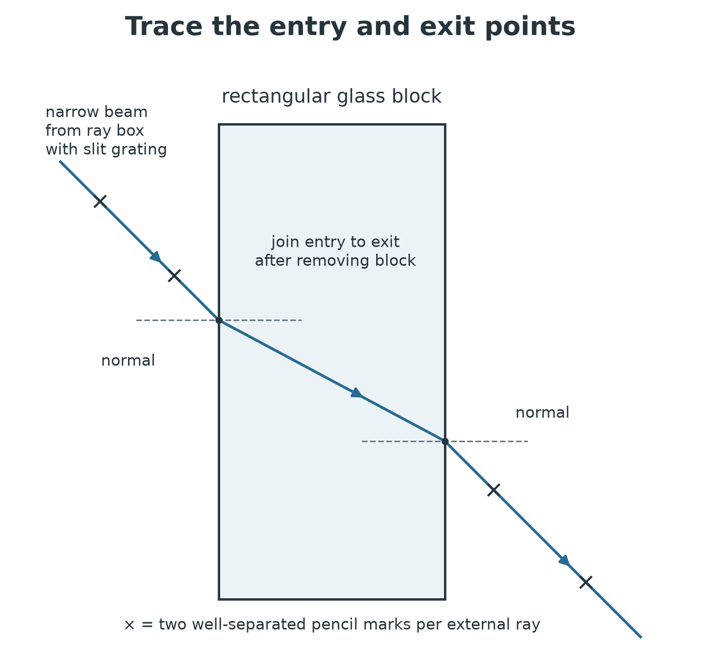
Use a ray box fitted with a single-slit grating and lens, a low-voltage power supply, connecting leads, a rectangular glass block, plain white paper, a sharp pencil, a ruler and a protractor. The single slit produces one narrow streak that can be traced accurately.
| Variable role | Quantity | How it is handled |
|---|---|---|
| Independent | Angle of incidence, i, in degrees | Set several well-spaced angles between the incident ray and the normal, such as 20 degrees to 60 degrees. |
| Dependent | Angle of refraction in the glass, r, in degrees | Reconstruct the internal ray and measure between it and the normal with a protractor. |
| Controlled | Glass material and block | Use the same rectangular block throughout. |
| Controlled | Light and geometry | Keep the same ray-box slit, light colour, entry face, point of incidence and block orientation. |
The main hazards are specific. A filament ray box can become hot, so do not touch the lamp housing during use and allow it to cool before moving it. Do not look directly into the bright beam; aim it across the bench and keep eyes above the ray path. Use the inspected low-voltage supply, keep leads tidy, and place the glass block flat and away from the bench edge.
Trace and measure the ray
- Put the glass block near the centre of a sheet of plain paper and draw closely around it with a sharp pencil. Mark one point near the middle of the left face as the point of incidence.
- Remove the block. Use a ruler and protractor to draw a normal through the marked point at exactly 90 degrees to that face.
- Choose an angle of incidence, for example 20 degrees. Measure it from the normal and draw a short guide line for the incident ray.
- Replace the block exactly inside its outline. Connect the ray box to its low-voltage supply, fit the single-slit grating and lens, and adjust them to make the narrowest clear streak.
- Aim the incident streak along the guide line so that it meets the marked point. Mark two small, well-separated crosses on the incident streak and two on the emergent streak. Also mark the points where the streak enters and leaves the block.
- Switch off the ray box and remove the block. Use a ruler to join the incident crosses to the entry point and the emergent crosses back to the exit point. Join the entry and exit points to reconstruct the refracted ray inside the block.
- Place the centre of the protractor on the point of incidence. Measure i between the incident ray and the normal, then measure r between the internal refracted ray and the same normal. Record both angles with the degree symbol.
- Repeat the complete alignment and tracing twice more at the same nominal value of i. Calculate the mean r, then repeat for at least four more well-spaced incident angles using a fresh sheet or uncluttered part of the paper.
Continue this lesson.
You’re previewing NovaLearn without an account. Create a free account to read the rest.
Create free account