13.5-13.7P - Transformers and turns ratio
A transformer changes an alternating voltage while keeping its input and output circuits electrically separate. Follow the changing magnetic field through its core, then use the turns ratio to calculate a voltage or a missing turn count. This lesson is Higher-tier content.
Two linked circuits
Imagine a small lamp connected to one coil of wire. The lamp can light when a second coil is connected to a low-voltage a.c. supply, even though no wire joins the two circuits. A transformer links the circuits magnetically instead of connecting them electrically.
A simple transformer has three main parts:
- the primary coil, connected to the alternating input potential difference;
- the secondary coil, connected to the separate output circuit;
- a closed iron core, which links the magnetic field through both coils.
The primary and secondary wires are insulated from one another and from the core. Charge does not cross the gap from the primary circuit to the secondary circuit, and current from the supply does not pass through the core to reach the secondary. (Real cores can have small circulating eddy currents, which cause unwanted heating.)
[DIAGRAM: asset_name: 52_1PH0-P2-13B_13.5-13.7P - Transformers and turns ratio - diagram 01; asset_slug: 52_1ph0-p2-13b_13-5-13-7p-transformers-turns-ratio_diagram_01; recommended_method: image_gen; description: Monochrome transformer schematic showing two electrically separate circuits, primary and secondary coils on a closed iron core, and the changing magnetic field linking them.]
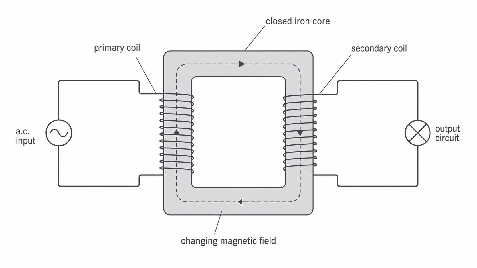
The arrows drawn inside the core represent the magnetic field direction at one instant. The field repeatedly changes and reverses; the arrows are not a permanently clockwise direction. They are part of a model of the field pattern, not material lines and not paths followed by charge.
The two electrical circuits are separate. Their link is a changing magnetic field in the iron core.
The induction chain
The input must keep changing for a transformer to keep working. Follow the causal chain carefully:
- An alternating potential difference across the primary coil drives an alternating current in the primary circuit.
- Because this current repeatedly changes in size and direction, its magnetic field also changes in strength and direction.
- The iron core links this changing magnetic field through the secondary coil.
- The changing magnetic field through the secondary coil induces an alternating potential difference across that coil.
- If the secondary is connected in a complete circuit, this induced potential difference drives an alternating current in the secondary circuit.
The changing field induces the potential difference; a current then flows only when there is a complete secondary circuit. This distinction matters: an open secondary can have an induced potential difference across its ends but has no continuous path for current.
A steady direct current would create a steady magnetic field after switch-on, so it would not produce continuous transformer action. Alternating current is needed because it continually changes the magnetic field.
How turns change voltage
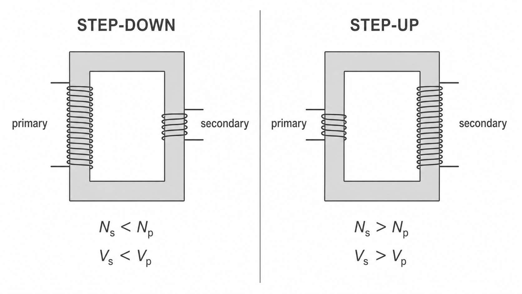
Each turn of the secondary coil links the changing magnetic field in the core. The induced potential differences around the turns add, so changing the number of turns changes the size of the alternating output voltage.
[DIAGRAM: asset_name: 52_1PH0-P2-13B_13.5-13.7P - Transformers and turns ratio - diagram 02; asset_slug: 52_1ph0-p2-13b_13-5-13-7p-transformers-turns-ratio_diagram_02; recommended_method: image_gen; description: Side-by-side monochrome comparison of step-down and step-up transformers, using visibly different coil turns and inequality labels to connect turns with alternating voltage.]
Continue this lesson.
You’re previewing NovaLearn without an account. Create a free account to read the rest.
Create free account