10.19-10.21 - LDRs, thermistors and sensing circuits
Investigate how light and temperature change resistance. Use paired voltage and current readings to compare an LDR, an NTC thermistor, a filament lamp and a diode fairly.
Resistance that responds to conditions
A fixed resistor is designed to have approximately constant resistance while its physical conditions stay constant. An LDR and a thermistor are different: their resistance changes when a condition around them changes. This makes them useful as sensing components.
Resistance is not a substance stored in a component. It describes how the component affects the relationship between the potential difference across it and the current through it. For one set of readings:
resistance = potential difference / current
Potential difference must be in volts (V) and current in amperes (A) to obtain resistance in ohms (ohm). If the current is recorded in milliamperes, convert it first: .
The equation also prevents a common error. A current reading by itself is not enough to determine resistance if the potential difference may also have changed; the current and potential difference must be recorded as a pair under the same condition.
How an LDR responds to light
An LDR, or light-dependent resistor, is a component whose resistance depends on the light intensity reaching it.
As light intensity increases, the resistance of an LDR decreases. As light intensity decreases, its resistance increases.
In bright light, an LDR therefore has a lower resistance than it has in dim light. It does not emit the light, and its resistance is not directly proportional to light intensity. Different LDRs have different exact curves, so the required relationship is the direction of the trend.
A fair test changes the light intensity at the LDR while keeping other conditions, especially temperature, as constant as possible. Ambient light should be controlled, and the light intensity should be measured with a light sensor or stated as a controlled relative level rather than guessed by eye.
How an NTC thermistor responds to temperature
A thermistor is a resistor whose resistance depends strongly on temperature. This lesson concerns only a negative temperature coefficient, or NTC, thermistor.
As temperature increases, the resistance of an NTC thermistor decreases. As temperature decreases, its resistance increases.
Negative describes the direction of the relationship: the temperature and resistance changes are opposite. For example, an NTC thermistor has a lower resistance in hot water than in cold water.
Do not turn this into a rule for every component. The metal filament in a lamp behaves differently: as a larger current heats the filament, its resistance increases. The component type and its physical condition must both be identified.
[DIAGRAM: asset_name: 42_1PH0-P2-10D_10.19-10.21 - LDRs, thermistors and sensing circuits - diagram 02; asset_slug: edexcel-gcse-physics-10-19-10-21-ldrs-thermistors-sensing-circuits_diagram_02; recommended_method: matplotlib; description: paired qualitative curve graphs with labelled axes showing LDR resistance decreasing with light intensity and NTC thermistor resistance decreasing as temperature rises]
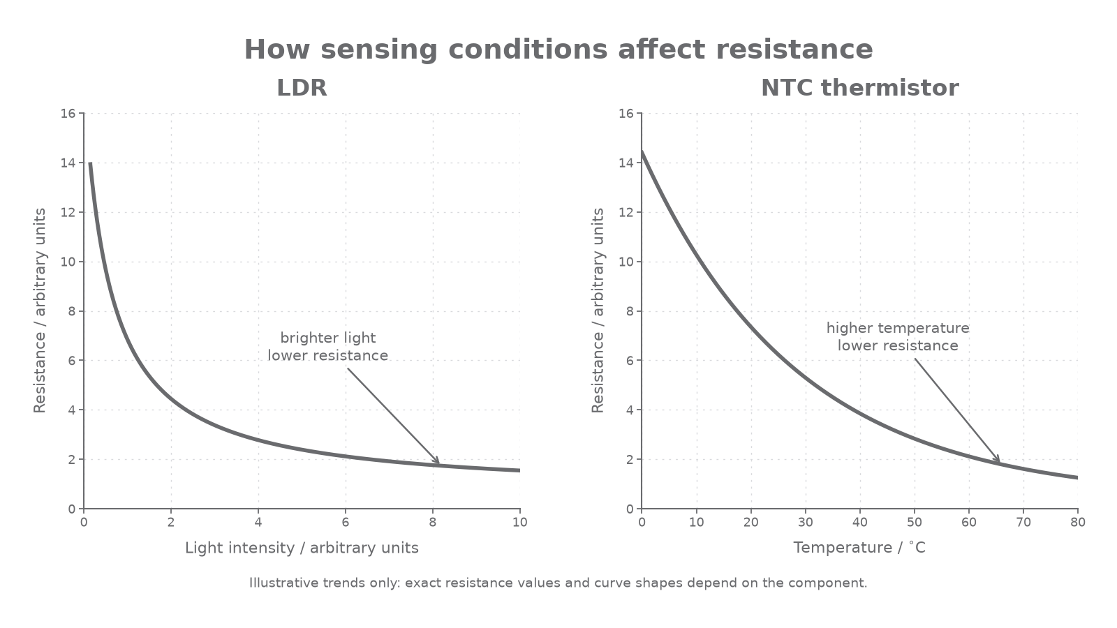
The plotted values are illustrative rather than calibration data for a particular component. In both panels the curve slopes down from left to right, but each horizontal axis represents a different physical condition.
Designing a circuit to measure changing resistance
One circuit can test any of the four required components. The device under test is replaced by a filament lamp, diode, thermistor or LDR as needed.
[DIAGRAM: asset_name: 42_1PH0-P2-10D_10.19-10.21 - LDRs, thermistors and sensing circuits - diagram 01; asset_slug: edexcel-gcse-physics-10-19-10-21-ldrs-thermistors-sensing-circuits_diagram_01; recommended_method: image_gen; description: accurate monochrome test circuit with power supply, switch, variable resistor and ammeter in series plus a voltmeter connected in parallel across the labelled device under test]
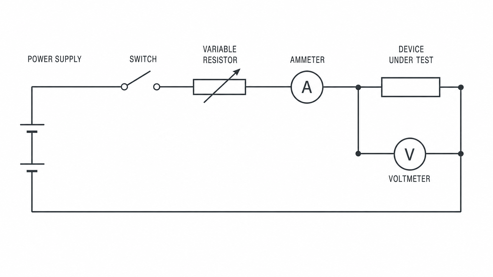
Each connection has a specific purpose:
| Component | Connection and role |
|---|---|
| power supply | provides a potential difference around the complete circuit |
| switch | isolates the circuit between measurements; keep it closed long enough for a filament lamp to reach a steady reading |
| variable resistor | is adjusted by the investigator to change the current and potential difference safely |
| ammeter | is connected in series to measure current through the device under test |
| voltmeter | is connected in parallel across the device under test to measure its potential difference |
Continue this lesson.
You’re previewing NovaLearn without an account. Create a free account to read the rest.
Create free account