10.17-10.18 - Circuit practical and I-V characteristics
Build and check circuits, collect current–voltage evidence for resistors and lamps, compare series with parallel, and explain the characteristic behaviour of resistors, lamps and diodes.
Measure resistor and lamp characteristics
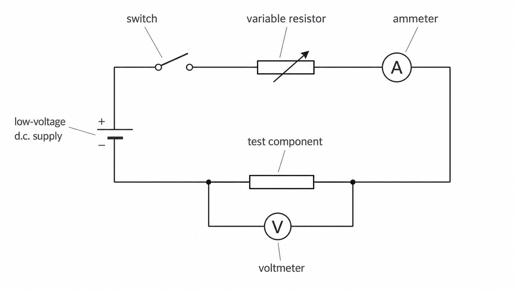
The first aim of core practical 10.17 is to investigate how current through a fixed resistor and a filament lamp varies with the potential difference across that component. Use the measurement circuit below with connecting leads, a switch, a low-voltage d.c. supply, a variable resistor, a digital ammeter, a digital voltmeter, a fixed resistor and a filament lamp.
[DIAGRAM: asset_name: 41_1PH0-P2-10C_10.15-10.18 - Circuit measurements and I-V core practical - diagram 01; asset_slug: 41_1ph0-p2-10c_10-15-10-18-circuit-measurements-and-i-v-core-practical_diagram_01; recommended_method: image_gen; description: A precise monochrome circuit diagram showing a low-voltage d.c. supply, switch, variable resistor, ammeter and test component in series, with a voltmeter connected only across the test component.]
| Variable role | Quantity | How it is handled |
|---|---|---|
| Independent | Potential difference across the tested component, in V | Change the variable resistor setting and record the actual voltmeter reading. |
| Dependent | Current through the tested component, in A | Read the series ammeter after the reading has settled. |
| Controlled | Component identity and connection | Use one component for a complete sweep, then replace only that component. |
| Controlled for the fixed resistor | Temperature | Use modest currents and open the switch between readings so heating does not change its resistance appreciably. |
| Measurement condition for the lamp | Stable temperature at each setting | Wait for the current to settle because heating of the filament is part of the behaviour being measured. |
- Build the circuit with the supply switched off. Put the fixed resistor, ammeter, variable resistor and switch in one series loop; connect the voltmeter across only the fixed resistor.
- Set the variable resistor to maximum resistance, choose the highest suitable ammeter range and have the connections checked before switching on.
- Close the switch briefly. Record the potential difference across the resistor and the current through it as a paired reading, then open the switch.
- Change the variable resistor to obtain at least six well-spaced positive values of , staying within every component rating. Record the actual meter readings rather than the power-supply dial value.
- Repeat the complete set twice more and calculate a mean current at each potential difference. If the settings cannot be reproduced exactly, choose a set of target voltages and adjust to each target while reading the voltmeter.
- Switch off. Reverse the supply connections so the current direction and meter signs reverse, then collect corresponding negative values. Never move leads while the circuit is live.
- Return the supply to zero, switch off, replace the fixed resistor with the filament lamp and repeat the positive and negative sweeps. At each setting, wait until the lamp reading is stable; allow the lamp to cool to a similar starting condition before each repeat sweep.
Plot current, , in A on the vertical axis against potential difference, , in V on the horizontal axis. Plot mean points and draw an appropriate line or smooth curve of best fit. Both axes include zero and negative values when both current directions were tested.
At any non-zero operating point, calculate resistance using:
Do not calculate at the origin. For a straight current-against-potential-difference line through the origin, its gradient is . For a curved characteristic, the resistance at a selected point is the ratio , not simply "the gradient of the graph".
The real hazards are excessive current and hot components. Use only the inspected low-voltage supply, keep its current limit active, start with high circuit resistance, and switch off before altering the circuit. Do not touch the lamp or resistor until it has cooled; keep leads tidy and replace any damaged lead.
Test series and parallel circuits
The second aim of core practical 10.17 is to test circuit rules by measurement. Use the same low-voltage supply and meter conventions with a pair of fixed resistors, then with a pair of identical filament lamps.
- Set a fixed supply potential difference and keep it unchanged for every comparison. With the supply off, connect two fixed resistors in series.
- Measure current at several positions in the single loop by moving one ammeter while the supply is off, or by using checked ammeters of suitable range. Measure the potential difference across each resistor and across the pair. Confirm that the current is the same and that the component potential differences add to the supply value.
- Reconnect the same resistors in parallel. Measure current in each branch and in the main wire. Measure potential difference across each branch and the supply. Confirm that the branch currents add to the total and that every branch has the supply potential difference across it.
- Calculate for each resistor and calculate the total circuit resistance from the supply potential difference and total current. Series connection raises the total resistance; parallel connection lowers it.
- Repeat the series and parallel tests with two identical filament lamps. Record current and potential difference as well as brightness, but use meter readings rather than brightness as the quantitative evidence.
Example measurements for two identical lamps at a 6.0 V supply illustrate the expected pattern:
| Lamp connection | Total current from supply (A) | Current through each lamp (A) | Potential difference across each lamp (V) | Brightness observation |
|---|---|---|---|---|
| Series | 0.28 | 0.28 | 3.0, 3.0 | both dimmer than in parallel |
| Parallel | 0.84 | 0.42, 0.42 | 6.0, 6.0 | both brighter than in series and similar to each other |
In series, the lamps carry the same current and share the supply potential difference. In parallel, each lamp receives the full supply potential difference, while the total current is the sum of the branch currents. The parallel total current is greater, so the total circuit resistance is lower. Lamp resistance is temperature-dependent, so it is not valid to assume that each lamp has one unchanged resistance in both arrangements.
Interpret I-V characteristics
[DIAGRAM: asset_name: 41_1PH0-P2-10C_10.15-10.18 - Circuit measurements and I-V core practical - diagram 02; asset_slug: 41_1ph0-p2-10c_10-15-10-18-circuit-measurements-and-i-v-core-practical_diagram_02; recommended_method: matplotlib; description: Three exact current-against-potential-difference graphs compare original illustrative data for a fixed resistor, filament lamp and diode, with labelled axes, scales, origins, data points and fitted characteristics.]
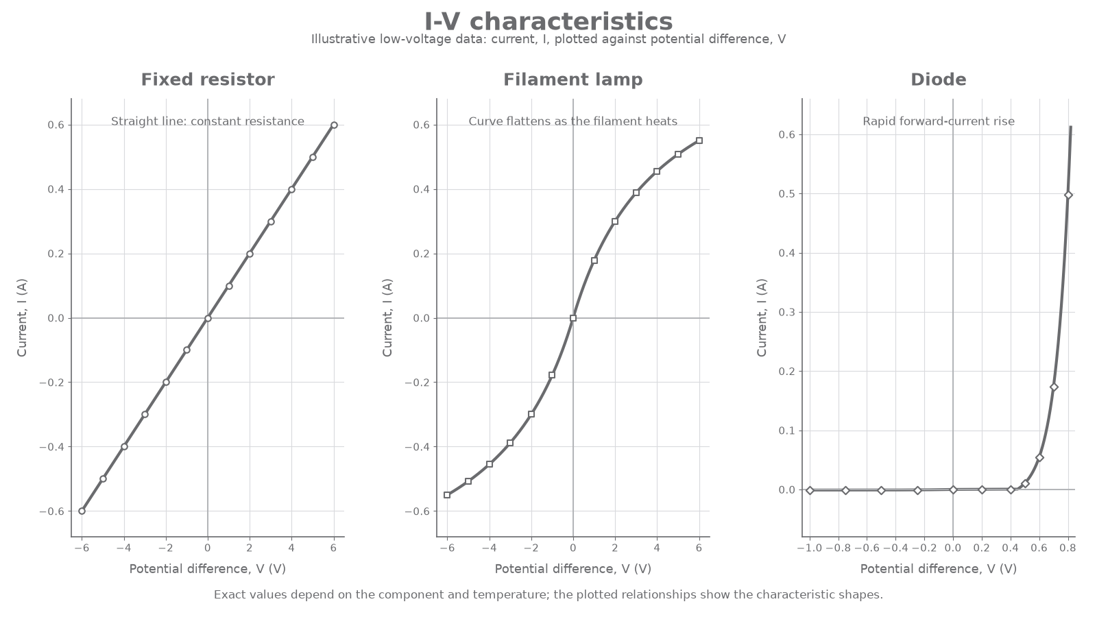
Read every panel as current against potential difference: horizontal position gives , vertical position gives , and each point represents one simultaneous meter-reading pair. The data are illustrative; the exact values for real lamps and diodes depend on the component and its temperature.
Fixed resistor
The fixed-resistor line is straight and passes through the origin. Doubling the potential difference doubles the current, so is constant while temperature remains approximately constant. For example, at and :
Continue this lesson.
You’re previewing NovaLearn without an account. Create a free account to read the rest.
Create free account