12.14P - How an electric motor turns
A motor uses magnetic forces to turn a coil. Follow two named sides through a half-turn to see why the contacts must reverse the coil current. This separate-Physics lesson is Higher-tier content and builds on the motor effect.
From a force to a turning effect
A simple direct-current motor has a rectangular coil mounted on an axle between magnetic poles. The coil and axle rotate together. A d.c. supply provides the current; the magnetic field is supplied by a permanent magnet or an electromagnet.
Current travels in opposite directions along the two long, active sides of the coil. Each side is perpendicular to the field. Fleming's left-hand rule therefore predicts opposite forces. Because the forces act on opposite sides of the axle, they produce a turning effect in the same rotational sense. Opposite forces can have zero resultant force while still turning an object.
View the motor end-on along its axle. Let the field point from left to right. Label the physical sides A and B so that they can be followed as the coil turns. At the illustrated starting position, A is on the left with current out of the page, so its force is upward. B is on the right with current into the page, so its force is downward. Both forces turn the coil clockwise in this view.
How the commutator keeps it turning
After half a turn, A is on the right and B is on the left. If current kept flowing in the same direction along each physical side, each side's force would stay the same and the turning effect would oppose continued rotation. The current must reverse at the appropriate stage of every half-turn.
The electrical contacts perform two different jobs:
- Brushes stay fixed and maintain sliding contact between the supply and the rotating commutator.
- The split-ring commutator consists of two conducting segments insulated from each other. Each segment connects to a different end of the coil and rotates with it. Every half-turn the segments exchange brushes, reversing the current in the coil.
[DIAGRAM: asset_slug: phy-f-motor-sequence-v2; description: End-on named motor sides with correct force and conventional-current directions, plus two distinct commutator contact positions half a turn apart.]
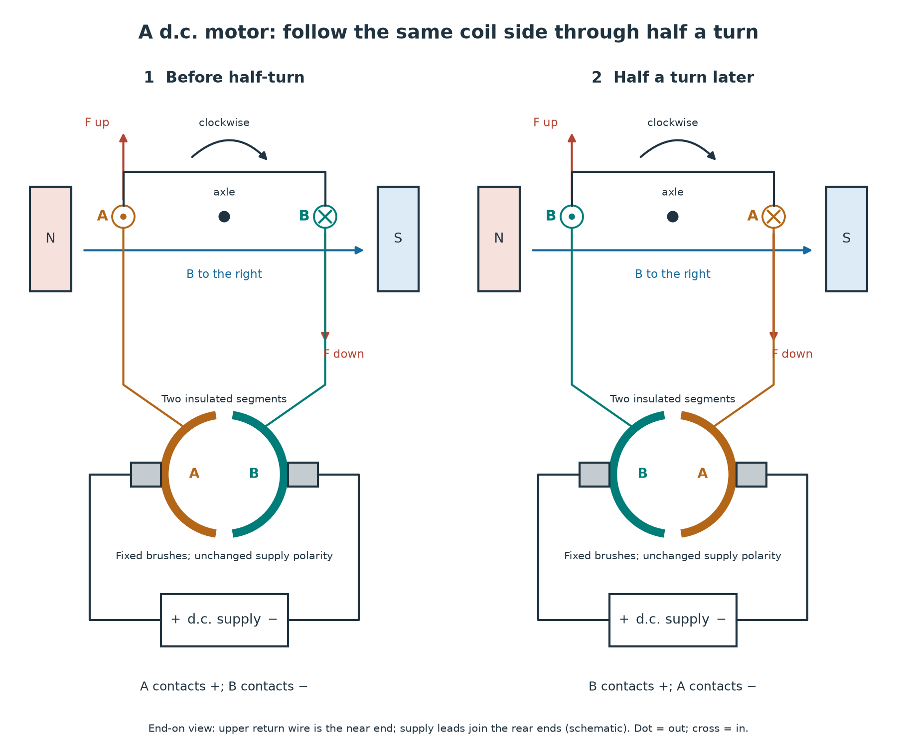
Follow A rather than just the left-hand position. A begins on the left with an upward force. Half a turn later it is on the right, its current is reversed and its force is downward. The turning effect is still clockwise. The supply polarity and magnetic field have stayed fixed; the rotating contacts changed which coil end was connected to each supply terminal.
During the turn, the perpendicular distance from the axle to each force's line of action changes, so the turning effect is not constant. At the central alignment it is momentarily zero. The commutator passes its insulating gaps at this stage and the coil's momentum carries it through. A simple single-coil motor may need a nudge if it starts at this position; practical motors use more than one coil to make starting and rotation smoother.
Continue this lesson.
You’re previewing NovaLearn without an account. Create a free account to read the rest.
Create free account