13.8-13.11P - National Grid and high-voltage transmission
High-voltage transmission reduces cable heating. Learn where grid transformers are used, calculate current using ideal-transformer power, and follow the energy to consumers. The final quantitative comparison, 13.11P, is separate-Physics Higher-tier content; 13.8–13.10 apply to both tiers.
From power station to home
A power station may need to transfer electrical energy to places many kilometres away. The cables are not perfect conductors: they have resistance, so a current transfers some energy to the thermal stores of the cables and their surroundings. The challenge is to deliver the required power while limiting this unwanted heating.
The National Grid is the system of cables and transformers that transfers electrical energy from generators to consumers. Its route has a deliberate order:
- A step-up transformer close to the power station increases the potential difference before long-distance transmission.
- Electricity is transferred through high-voltage transmission cables. For a given transmitted power, the higher potential difference allows a smaller current.
- Step-down transformers at substations reduce the potential difference in stages as electricity enters local distribution networks.
- Electricity reaches homes at a much lower potential difference that is suitable for domestic use.
[DIAGRAM: asset_name: 53_1PH0-P2-13C_13.8-13.11P - National Grid and high-voltage transmission - diagram 01; asset_slug: 53_1ph0-p2-13c_13-8-13-11p-national-grid-high-voltage-transmission_diagram_01; recommended_method: image_gen; description: monochrome left-to-right National Grid route showing power station, step-up transformer, high-voltage transmission pylons, local step-down transformer and homes with unambiguous transfer arrows]
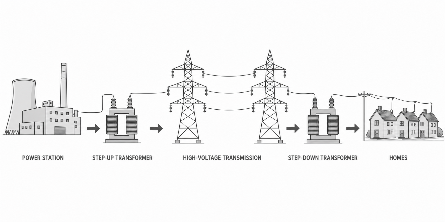
The arrows in the diagram show the route through the system; they are not arrows for current direction and do not suggest that energy is a material carried inside the wire. Transformers require an alternating voltage, so the National Grid uses a.c. where transformers change voltage.
The two transformer types have opposite jobs:
| Transformer | Where it is used | What it does and why |
|---|---|---|
| step-up | near a power station, before long-distance cables | increases potential difference and reduces current for the power being transferred, limiting cable heating |
| step-down | at substations after transmission and within local distribution | decreases potential difference to levels suitable for local and domestic use |
Power in an ideal transformer
A transformer has a primary coil connected to the input supply and a secondary coil connected to the output circuit. In the ideal model used by statement 13.10, the transformer is 100% efficient. No power is dissipated by the transformer, so its input power equals its output power.
For any electrical transfer, . Applying this relationship to both coils gives:
For a 100%-efficient transformer: input power = output power.
- and are the primary and secondary potential differences in volts (
V). - and are the primary and secondary currents in amperes (
A). - each product has the unit watt (
W).
The ideal-transformer power equation is provided on the Pearson Physics equation sheet and applies at both tiers. You still need to identify the primary and secondary values, convert prefixes, rearrange correctly and give the answer with a unit.
In an ideal step-up transformer, is larger than , so must be smaller than to keep the products equal. In an ideal step-down transformer, the secondary voltage is smaller and the secondary current is larger. A transformer changes the voltage-current combination; it does not create power.
Worked example
An ideal step-up transformer receives 11 kV at a current of 1200 A. Its secondary potential difference is 275 kV. Calculate the secondary current.
Convert the potential differences:
Choose the equation and rearrange:
Substitute:
The secondary current is 48 A, to two significant figures. The voltage has increased by a factor of 25, while the current has decreased by a factor of 25. Both sides represent 13.2 MW, so the result is consistent with the 100%-efficient model.
Why high voltage reduces heating
The grid must transfer a required power, not merely a voltage or a current. The relationship shows that the same power can be transferred using different voltage-current combinations.
Continue this lesson.
You’re previewing NovaLearn without an account. Create a free account to read the rest.
Create free account