10.7-10.11 - Current, charge and junctions
Follow charge around a complete circuit, measure its flow with an ammeter and use conservation of charge to explain junction currents.
Current in a closed circuit
Consider a cell, a switch and a lamp joined by metal wires. The metal already contains mobile electrons, whether the switch is open or closed. Closing the switch completes an unbroken conducting path, and the cell provides a potential difference across that path. The electrons then have a net drift through the metal, so there is an electric current around the circuit.
Open the switch and the conducting path is broken. The source still has a potential difference between its terminals, but there is no complete route, so there is no steady current around the whole circuit. A closed circuit that includes a source of potential difference is therefore needed for a sustained current.
Electric current is the rate of flow of electric charge. In a metal, the moving charge carriers are electrons. Current is measured in amperes, A.
Current is not a store of charge that a component gradually uses up. It tells us how much charge passes a point each second. In metal wires, negatively charged electrons drift from the negative terminal towards the positive terminal. Circuit arrows normally show conventional current in the opposite direction, from the positive terminal towards the negative terminal.
An ammeter measures the current in a component. It must be connected in series with that component, so the charge passing through the component also passes through the meter. Placing an ammeter on a separate parallel route would not measure the component's current and could provide a very low-resistance path.
[DIAGRAM: asset_name: 40_1PH0-P2-10B_10.7-10.14 - Current, resistance and circuit rules - diagram 01; asset_slug: 40_1ph0-p2-10b_10-7-10-14-current-resistance-and-circuit-rules_diagram_01; recommended_method: image_gen; description: monochrome closed circuit with a cell, closed switch, resistor and ammeter in one unbroken loop, showing conventional current arrows opposite clearly labelled electron drift arrows]
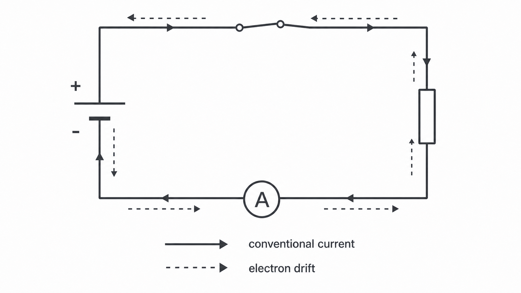
In the diagram, the ammeter and resistor lie on the same single route. The two arrow sets describe the same current using different sign conventions: electrons move one way, while conventional current is defined in the opposite direction.
Charge, current and time
Because current is a rate, an ammeter reading of means that of charge passes each second:
This definition gives the relationship between charge , current and time .
- is charge in coulombs, C
- is current in amperes, A
- is time in seconds, s
This relationship is included in the supplied equation support; practise choosing it, using consistent units and rearranging it. You still need to choose it, use compatible units and rearrange it when necessary.
Worked example
An ammeter reads for . Calculate the charge that passes.
First convert the time:
Choose the relationship and substitute:
The data are given to two significant figures, so is suitable. The result is sensible: passes each second, and over that must be many tens of coulombs.
To find current instead, rearrange before substituting:
Continue this lesson.
You’re previewing NovaLearn without an account. Create a free account to read the rest.
Create free account