3.5.1.6 - Electromotive Force and Internal Resistance
Every battery you use -- from the one in your phone to the cells in a physics lab -- wastes some of the energy it produces just pushing charge through itself. This happens because all real sources of electrical energy have internal resistance. Understanding this concept is essential for analysing realistic circuits and explains why the voltage you measure across a battery's terminals is often less than the value printed on its label.
Part 1: Electromotive Force
Electromotive Force (emf)
The electromotive force (emf) of a source is the energy transferred per unit charge by the source in driving charge around a complete circuit. It is measured in volts (V).
Despite its name, emf is not a force -- it is an energy transfer per unit charge (J C), which is dimensionally identical to potential difference. The key distinction is that emf refers to the total energy the source provides to each coulomb, whereas potential difference refers to the energy transferred by a component.
EMF from Energy and Charge
Here is the emf in volts (V), is the total energy transferred by the source in joules (J), and is the charge that flows in coulombs (C). This equation is given in the AQA data booklet.
The emf of a source can be measured by connecting a high-resistance voltmeter directly across its terminals when no current is flowing (i.e., in an open circuit). Under these conditions, no energy is lost to internal resistance, so the voltmeter reading equals the emf.
Part 2: Internal Resistance
Internal Resistance
The internal resistance of a source is the resistance within the source itself, caused by opposition to the flow of charge through the source. It results in energy being dissipated inside the source when current flows.
When charge flows through a cell, electrons collide with atoms and ions inside the cell. These collisions transfer kinetic energy to the internal structure of the cell, heating it up. This means that some of the electrical energy produced by the cell is wasted before it even reaches the external circuit.
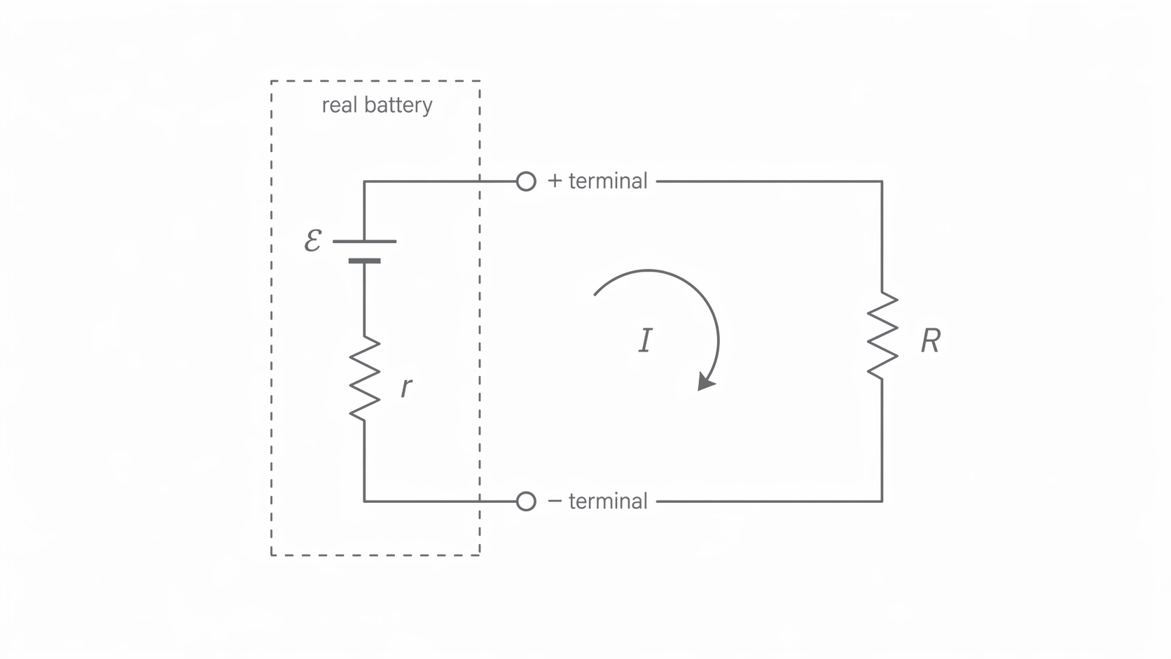
In circuit diagrams, internal resistance is represented as a small resistor of resistance drawn in series with an ideal cell of emf , as shown below. In this model, notice that the small resistor is inside the battery boundary and still in series with the external resistor, so the same current flows through both.
[DIAGRAM: asset_name: 5.1.6 - Electromotive Force and Internal Resistance - Diagram 1; asset_slug: 5.1.6 - Electromotive Force and Internal Resistance - Diagram 1; recommended_method: retained_png; description: A cell represented as an ideal emf source (labelled epsilon) in series with a small resistor (labelled r) inside a dashed box representing the real battery. The dashed box has two terminals connecting to an external circuit containing a resistor R. Current I flows clockwise around the circuit.]
Since the internal resistance is in series with the external (load) resistance , the total resistance of the circuit is simply:
Applying Ohm's law to the whole circuit gives the emf equation:
EMF Equation
This can be expanded as:
where is the current in the circuit (A), is the external resistance (), and is the internal resistance (). On the current AQA data and formulae sheet, both and are provided. The exam skill is recognising that is the total circuit resistance, then rearranging the equation correctly for the quantity you need.
Terminal Potential Difference
The terminal pd () is the potential difference across the external terminals of a source when current is flowing. It equals the energy per unit charge delivered to the external circuit.
This is the useful share of the emf that reaches the external circuit. The remainder is dropped inside the source itself.
Lost Volts
Lost volts () is the potential difference across the internal resistance of a source. It represents the energy per unit charge dissipated (wasted) inside the source.
From the emf equation, we can identify:
- Terminal pd: (the useful pd delivered to the external circuit)
- Lost volts: (the pd wasted inside the cell)
Therefore:
EMF as Sum of Terminal pd and Lost Volts
This tells us that the emf is always shared between the terminal pd and the lost volts. The terminal pd is always less than the emf whenever current flows, because some voltage is always dropped across the internal resistance.
Part 3: Circuit Calculations with Internal Resistance
The emf equation can be rearranged to solve for any unknown quantity. Let us work through the key rearrangements.
Because is already supplied on the current AQA sheet, most questions are really testing whether you can decide when to treat the cell and load as one series circuit, and when to switch to the terminal-pd form.
To find the current in a circuit:
To find the internal resistance:
To find the external resistance:
Here is a worked example demonstrating the standard approach.
Worked Example 1: A battery of emf 12 V and internal resistance 1.5 is connected to a 4.5 resistor. Calculate (a) the current through the battery, (b) the lost pd, and (c) the terminal pd.
(a) Using :
(b) Lost volts: V
(c) Terminal pd: V
Alternatively: V (confirming the answer).
Now consider a slightly more complex scenario involving lost volts.
Worked Example 2: A cell has an emf of 5 V and lost volts of 2 V. The external resistance is 10 . Find the current in the circuit.
The terminal pd is: V
Using : A
Part 4: The V-I Graph Method
Rearranging gives:
Terminal pd as a Function of Current
Compare this with the equation of a straight line :
| Straight-line form | EMF equation |
|---|---|
| (terminal pd) | |
| (gradient) | (negative of internal resistance) |
| (current) | |
| (-intercept) | (emf) |
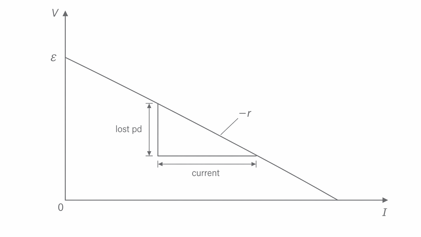
So if you plot terminal pd () on the -axis against current () on the -axis, you get a straight line. The graph below is the one to picture in an experiment; notice that the -intercept gives and that the downward gradient has magnitude .
- The -intercept gives the emf (because at , ).
- The gradient equals , so the magnitude of the gradient gives the internal resistance.
[DIAGRAM: asset_name: 5.1.6 - Electromotive Force and Internal Resistance - Diagram 2; asset_slug: 5.1.6 - Electromotive Force and Internal Resistance - Diagram 2; recommended_method: retained_png; description: A graph with current I on the x-axis and terminal pd V on the y-axis. A straight line with negative gradient starts at the y-intercept (labelled epsilon) and slopes downward. A gradient triangle is drawn on the line, with the vertical side labelled "lost pd" and the horizontal side labelled "current". The gradient is labelled as -r.]
This graphical method is the standard experimental technique for determining both the emf and internal resistance of a cell. The experimental setup consists of a cell connected in series with a variable resistor, an ammeter, and a switch, with a voltmeter connected directly across the cell terminals. By adjusting the variable resistor, different pairs of and readings are obtained.
This graphical method is used in battery testing for electric vehicles and portable electronics. Engineers measure the terminal voltage at different discharge currents to determine the internal resistance of battery packs. A low internal resistance is critical -- in a high-current application like an electric car, a large internal resistance would waste significant power as heat inside the battery, reducing both efficiency and range.
The internal resistance and emf can also be calculated algebraically from just two pairs of measurements. If the terminal pd is at current and at current , then:
Subtracting:
The emf can then be found by substituting back into either equation.
Part 5: Using the Formula Sheet Well
On the current AQA data and formulae sheet, students are given both and . In exam conditions, the challenge is usually not remembering the equation but choosing the right version of it for the circuit in front of you.
A reliable routine is:
- Identify whether the question is about the whole circuit, the external resistor, or the cell terminals.
- For the whole circuit, use or .
- For the useful output across the external resistor, use and then connect it back to the cell with .
- For a graph of terminal pd against current, read from the -intercept and from the magnitude of the gradient.
A quick sense-check helps. If the current increases, the lost volts must increase, so the terminal pd must decrease. Any answer that makes the terminal pd bigger than the emf while current is flowing is automatically wrong.
Part 6: Bringing It All Together
The relationships between emf, internal resistance, terminal pd, and lost volts are summarised below.
| Quantity | Symbol | Expression | Meaning |
|---|---|---|---|
| Electromotive force | Total energy per coulomb from the source | ||
| Internal resistance | -- | Resistance inside the source | |
| Terminal pd | Useful voltage delivered to the external circuit | ||
| Lost volts | Voltage wasted inside the source |
Key points to remember:
- At zero current (open circuit): and .
- As current increases: decreases and increases, but remains constant.
- At short circuit (): all voltage is dropped across , giving and .
The emf of a source is fixed by its chemistry (or physics), but the terminal pd depends on how much current is drawn. Every increase in current means more energy wasted internally, leaving less for the external circuit.
That single idea explains both the straight-line graph and the everyday observation that a battery voltage sags when the battery is under load.