3.5.1.5 - Potential Divider
In many circuits we need a specific voltage that is lower than the supply voltage, or a voltage that changes in response to environmental conditions such as temperature or light level. A potential divider is an elegantly simple arrangement of resistors in series that lets us tap off any fraction of the source pd we require. This topic draws together your knowledge of series circuits, Ohm's law, and special resistors (thermistors and LDRs) into one of the most practically useful circuit configurations in A-level physics.
1. The Potential Divider Principle
Potential Divider
A potential divider is a circuit consisting of two or more resistors connected in series across a source of potential difference, arranged so that a fraction of the source pd can be tapped off across one of the resistors.
Consider two resistors, and , connected in series across a source of fixed pd . Because the resistors are in series, the same current flows through both. The diagram below shows the standard divider layout; notice that the output is taken across , so the fraction of the source pd you tap off depends on how large is compared with the total resistance.
[DIAGRAM: asset_name: 5.1.5 - Potential Divider - Diagram 1; asset_slug: 5.1.5 - Potential Divider - Diagram 1; recommended_method: retained_png; description: Two resistors R1 and R2 in series connected across a battery of pd V0. The current I flows clockwise. The pd V1 is labelled across R1 and V2 is labelled across R2. An output terminal is shown across R2.]
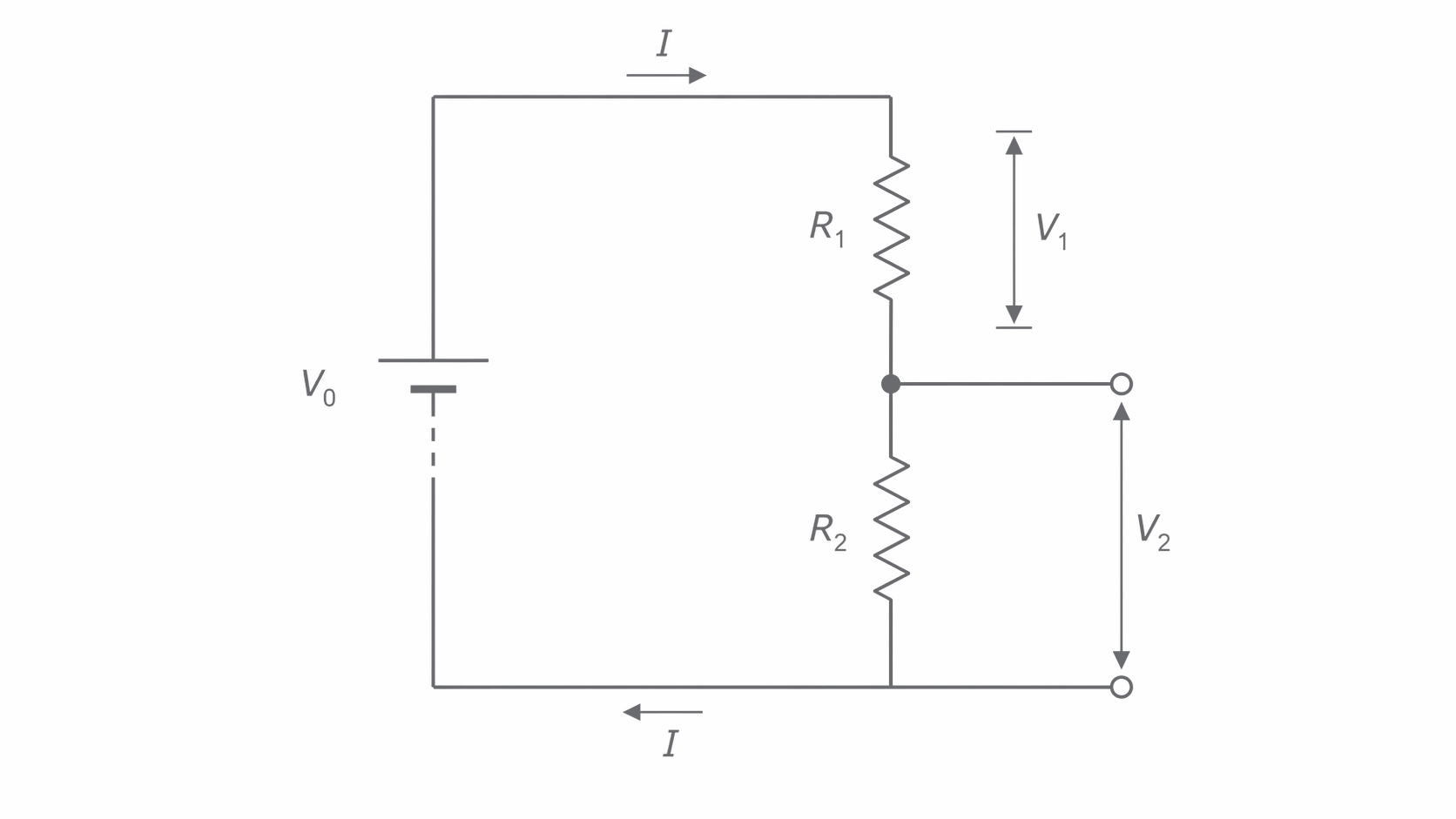
The total resistance of the series combination is , so the current through both resistors is:
Using for each resistor individually, we can write the pd across each one.
Potential Divider Equation
Here is the source pd, and are the two resistor values, and and are the pds across and respectively. This equation is not given in the data booklet -- you must be able to recall and derive it from first principles using and the series current rule.
The key insight is that the pd across each resistor, as a fraction of the source pd, equals the resistance of that resistor as a fraction of the total resistance. Dividing the two expressions also gives us a useful ratio form:
This tells us the pds are shared in the same ratio as the resistances.
In a potential divider, the output pd is determined by the ratio of the resistances, not their absolute values. Doubling both resistances gives the same output pd (though it halves the current drawn from the supply).
For example, if and are connected across a supply, the pd across is:
and the pd across is . Notice that has twice the resistance of and receives twice the pd.
2. Supplying a Variable Potential Difference
A potential divider can supply a continuously variable pd by replacing one of the fixed resistors with a variable resistor, or more commonly by using a length of uniform resistance wire with a sliding contact. In the sketch below, notice that the contact position selects a matching fraction of the total wire length , so it also selects the matching fraction of the source pd at the output.
[DIAGRAM: asset_name: 5.1.5 - Potential Divider - Diagram 2; asset_slug: 5.1.5 - Potential Divider - Diagram 2; recommended_method: retained_png; description: A battery connected to a length of uniform resistance wire. A sliding contact on the wire can be moved along its length. The output pd is taken between the sliding contact and one end of the wire. Label the total length L and the contact position at distance x from one end.]
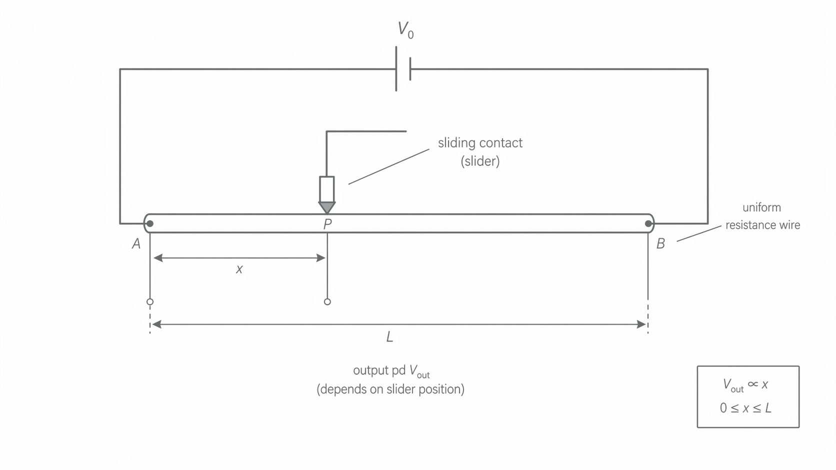
As the sliding contact is moved along the wire, the effective resistance on each side of the contact changes. If the wire has total resistance and the contact is a fraction along its length, then one side has resistance and the other side has resistance . The output pd therefore varies continuously from zero (contact at one end) to the full source pd (contact at the other end).
This is the operating principle of a potentiometer used as a variable potential divider. The circuit symbol shows a resistor with an arrow indicating the sliding contact. Variable potential dividers of this type can be built with either a linear track or a circular track.
Audio volume controls in amplifiers and mixing desks use rotary potentiometers as variable potential dividers. The audio signal pd is fed to the potentiometer, and the sliding contact taps off a variable fraction of it before sending it to the loudspeaker or headphones. Turning the dial moves the contact, smoothly varying the output pd and hence the volume.
A key advantage of using a potential divider to vary the pd supplied to a component (such as a lamp) is that the output pd can be varied all the way from zero to the full source pd. In contrast, placing a simple variable resistor in series with the lamp can only reduce the current -- it can never reduce the pd across the lamp to zero because there would still be a current through the lamp even at maximum resistance.
3. Sensor Circuits: Thermistors and LDRs
One of the most important applications of the potential divider is in sensor circuits. By replacing one of the fixed resistors with a component whose resistance changes with a physical condition, the output pd of the divider changes in response to that condition.
Sensor Circuit
A sensor circuit is a potential divider in which one resistor is replaced by a sensing component (such as a thermistor or LDR), so that the output pd changes when the physical variable being measured (temperature, light intensity, etc.) changes.
Temperature sensor using a thermistor
Recall that a negative temperature coefficient (NTC) thermistor has a resistance that decreases as temperature increases. When a thermistor is used in a potential divider alongside a fixed resistor , the output pd changes with temperature. In the circuit below, notice that the voltmeter is connected across the fixed resistor, which is why a fall in thermistor resistance makes the output pd rise.
[DIAGRAM: asset_name: 5.1.5 - Potential Divider - Diagram 3; asset_slug: 5.1.5 - Potential Divider - Diagram 3; recommended_method: retained_png; description: A battery of pd V0 connected in series with a thermistor (labelled R_T, top) and a fixed resistor R (bottom). The output pd V_out is measured across the fixed resistor R. A voltmeter is shown connected across R.]
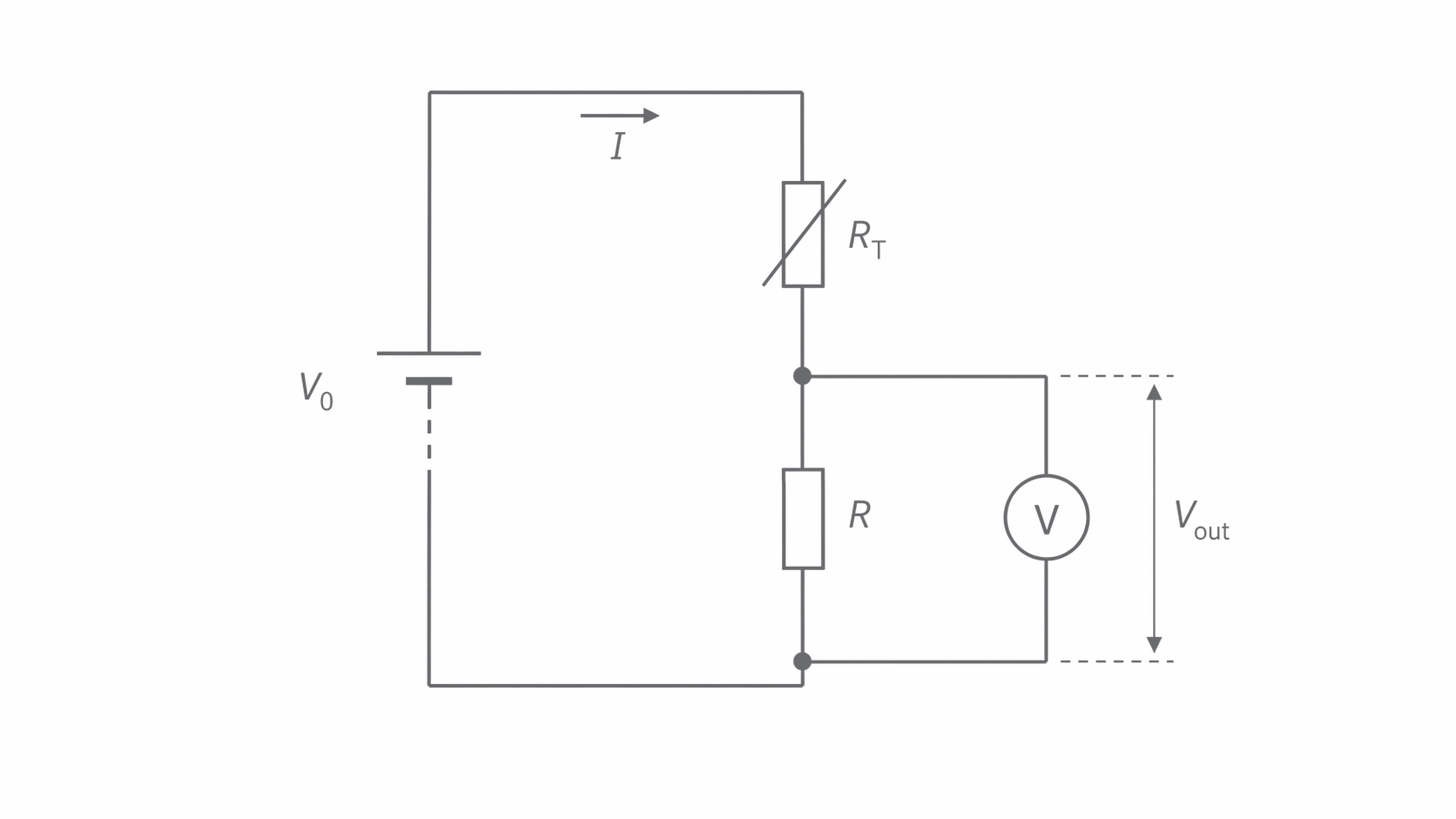
Using the potential divider equation, the pd across the fixed resistor is:
When the temperature increases, decreases, so the total resistance decreases, the circuit current increases, and across increases.
Conversely, if the output is taken across the thermistor itself:
In this case, when temperature increases and falls, decreases.
The position of the sensing component in the divider therefore determines whether the output pd increases or decreases with the physical variable.
Light sensor using an LDR
A light-dependent resistor (LDR) has a resistance that decreases as light intensity increases. In a potential divider with a fixed resistor, the LDR can be used as a light sensor. The diagram below mirrors the thermistor circuit, but notice that the sensing component is now an LDR, so the same divider logic now turns changes in light level into changes in .
[DIAGRAM: asset_name: 5.1.5 - Potential Divider - Diagram 4; asset_slug: 5.1.5 - Potential Divider - Diagram 4; recommended_method: retained_png; description: A battery of pd V0 connected in series with an LDR (labelled R_LDR, top) and a fixed resistor R (bottom). The output pd V_out is measured across R. A voltmeter is shown connected across R.]
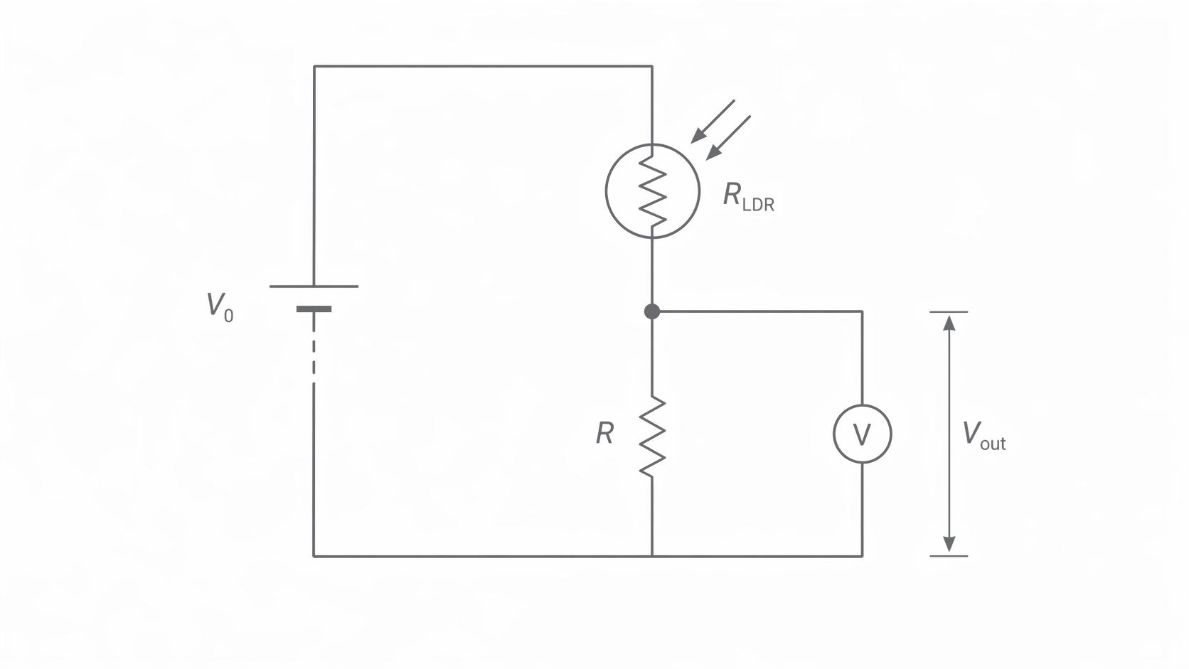
If the output pd is taken across the fixed resistor :
When light intensity increases, decreases, so the total resistance falls, current increases, and increases. This configuration could be used to trigger an event (such as switching on a warning light) when the ambient light level rises above a threshold.
If the output is taken across the LDR instead, then
As light intensity increases, decreases, so the pd across the LDR decreases. This means the reversed arrangement gives a larger output pd in the dark, so it can be used to switch on a lamp when the output rises above a threshold voltage.
Automatic outdoor lighting systems use LDR-based potential dividers to detect falling light levels at dusk. The output pd of the divider is fed to a comparator circuit or transistor switch. When the pd crosses a set threshold (corresponding to a particular light level), the system activates the lights. A variable resistor in the divider allows the sensitivity (the light level at which switching occurs) to be adjusted.
The same logic appears in calculations as well as in real control circuits, so it is worth checking that you can move smoothly from a qualitative description to a numerical value of .
4. Worked Example and Problem-Solving Strategy
When tackling potential divider problems, follow this systematic approach:
- Identify the two resistances in the divider (they may be fixed resistors, a thermistor, an LDR, or sections of resistance wire).
- Identify where the output pd is taken -- across which component?
- Apply the potential divider equation using , where is the resistance of the component across which the output is measured.
- Check your answer -- the output pd must be less than or equal to , and the pds across both resistors must add up to .
Worked example
A light sensor consists of a cell of negligible internal resistance, an LDR, and a resistor in series. A voltmeter is connected in parallel with the resistor and reads when the LDR is in darkness.
(a) Calculate the pd across the LDR.
Since the resistors are in series and the cell has negligible internal resistance, the pds must sum to the source pd:
(b) Calculate the resistance of the LDR.
Using the ratio property of potential dividers:
(c) Describe and explain what happens to the voltmeter reading when the LDR is exposed to daylight.
When the LDR is exposed to daylight, the light intensity increases, so the resistance of the LDR decreases. This means the total resistance of the circuit decreases and the current increases. Since a smaller fraction of the total resistance is now in the LDR, a smaller fraction of the source pd falls across the LDR and a larger fraction falls across the fixed resistor. The voltmeter reading therefore increases.
5. Qualitative Reasoning and the Effect of Changing Conditions
Exam questions frequently ask you to describe and explain how the output pd of a sensor circuit changes when conditions change. You must be able to construct a clear chain of reasoning.
The standard logical chain is:
- State what happens to the physical variable (e.g. "temperature increases").
- State the effect on the sensing component's resistance (e.g. "the thermistor's resistance decreases").
- State the effect on the total circuit resistance and current (e.g. "total resistance decreases, so current increases").
- State the effect on the output pd, explaining which component now has a larger or smaller share of the source pd (e.g. "a larger fraction of the pd now falls across the fixed resistor, so increases").
This chain of reasoning -- physical change, resistance change, current change, pd redistribution -- is the template for virtually every qualitative potential divider question.
It is also important to recognise that swapping the positions of the two components in the divider reverses the response. If a circuit is designed so that increases when it gets warmer, switching the thermistor and fixed resistor would make decrease when it gets warmer.
That spoken chain is the same structure you want in a longer exam answer: identify which component is measured across, state how the sensor resistance changes, then explain how the pd is redistributed.
Final recall task: before doing any potential-divider calculation, state out loud which component is across. In the worked LDR calculation above, is across the fixed resistor, not across the LDR.