3.4.1.4 - Projectile Motion
A projectile problem becomes manageable once you split one curved path into two simpler motions. In the ideal model, gravity changes only the vertical motion while the horizontal motion continues independently. After that, we can add the real-world complications the specification wants qualitatively: friction, drag, lift, terminal speed, and the factors that limit the maximum speed of a vehicle.
Part 1: Horizontal and Vertical Motion
The core idea is independence. In a uniform gravitational field, gravity acts vertically downward, so it changes the vertical component of motion but not the horizontal component. If air resistance is negligible, horizontal motion is constant-velocity motion while vertical motion is constant-acceleration motion.
Projectile
An object acted on only by gravity. If air resistance is negligible, its acceleration is always vertically downward.
Because the two directions are independent, every projectile question can be split into a horizontal part and a vertical part. The link between them is the time , which is the same in both directions.
Component equations in a uniform gravitational field
Here is horizontal displacement, is the horizontal component of the initial velocity, is vertical displacement measured upward from the launch point, and is the initial vertical component. If you want the speed at any instant, combine the components using .
The classic demonstration is to drop one ball from rest while projecting another horizontally from the same height at the same instant. They hit the ground together because their vertical motion is identical: both start with zero vertical velocity and both accelerate downward at .
Part 2: Resolving the Initial Velocity
When a projectile is launched at speed and angle above the horizontal, you must resolve the initial velocity into horizontal and vertical components before using SUVAT.
Resolving launch speed
For a horizontal launch, so and the whole launch speed is horizontal. For a vertical launch, . For launches below the horizontal, the vertical component is negative if you take upward as positive.
The diagram below shows the velocity triangle you should sketch first; notice how the launch-speed vector splits into the horizontal component and the vertical component .
[DIAGRAM: asset_name: 4.1.4 - Projectile Motion - Diagram 1; asset_slug: 4.1.4 - Projectile Motion - Diagram 1; recommended_method: retained_png; description: A launch-speed vector at angle above the horizontal, resolved into a horizontal component and a vertical component to form a right-angled triangle.]
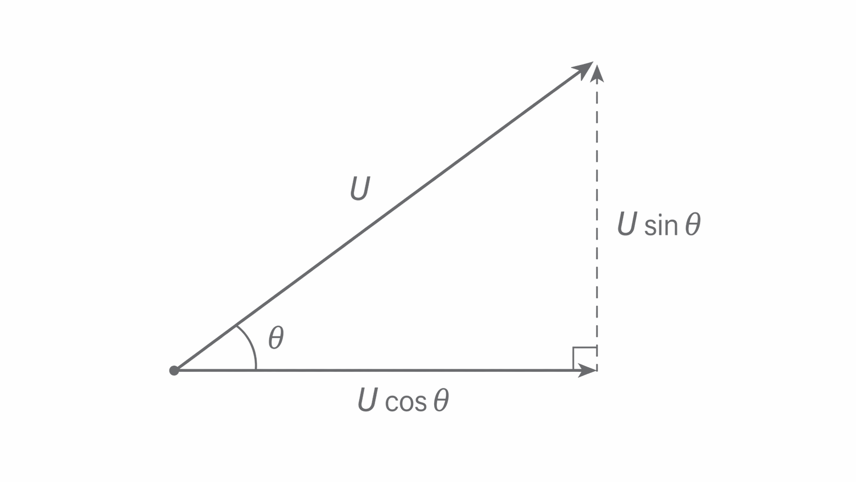
For example, if and , then and . Once those two values are known, the rest of the problem is usually much simpler.
Part 3: Horizontal Projection
In a horizontal projection, the initial vertical velocity is zero. That means the vertical motion is just free fall, so it usually makes sense to find the time of flight first and then use that time in the horizontal direction.
Horizontal projection from a height
Here is the vertical drop, so we treat downward displacement as positive for convenience. The key idea is that the time of flight depends on the height, not on the horizontal speed.
Worked Example
An object is projected horizontally at from the top of a tower of height . Calculate the time to reach the ground, the horizontal distance travelled, and the speed just before impact. Take .
From the vertical motion:
The horizontal distance is then
The vertical speed just before impact is
So the impact speed is
This example shows the usual pattern: vertical motion gives the time, horizontal motion gives the range, and the two components combine to give the final speed.
Part 4: Angled Projection
When a projectile is launched at an angle, the vertical initial velocity is no longer zero, so the projectile rises before it falls. The method is still the same: resolve the launch speed, solve the vertical motion, and use the same time in the horizontal motion.
If the projectile lands at the same height it was launched from, three useful results follow from SUVAT and symmetry.
Useful results for level launch and landing
These results are only for launch and landing at the same vertical level, with air resistance neglected. They are useful checks, but the safest approach is still to build the answer from resolved components and the SUVAT equations.
Worked Example
A ball is projected from level ground at at to the horizontal. Find the maximum height and total time of flight. Take .
First resolve the initial velocity:
At maximum height, , so
The time to the top is
So the total time of flight is
The symmetry matters here: because the ball lands at the same height, the ascent time equals the descent time.
Part 5: Resistive Forces and Maximum Speed
Real projectiles and real vehicles move through air and along surfaces, so resistive forces matter. The specification only needs a qualitative treatment here, but the ideas are important.
Friction and drag
Friction is a force that opposes relative motion between surfaces in contact. Drag is the resistive force on an object moving through a fluid; it acts opposite to the motion and increases with speed.
Lift is an upward force that can arise when the motion of a fluid creates a pressure difference above and below an object. Wings are designed to create useful lift, while spinning balls can experience lift in different directions depending on the spin.
Terminal speed
The constant speed reached when the driving force is balanced by the total resistive force, so the resultant force is zero and the acceleration is zero.
For a falling object, the driving force is usually its weight. At first, weight is bigger than drag, so the object accelerates. As speed rises, drag increases. Eventually drag equals weight, so the object continues at constant speed.
Time-trial cyclists crouch low and wear smooth helmets to reduce drag. A smaller frontal area and a more streamlined shape reduce the resistive force, so the same rider can maintain a higher steady speed.
For a vehicle on a level road, maximum speed is reached when the driving force from the engine or motor equals the total resistive force. The main factors that affect that maximum speed are:
- the size of the driving force available from the engine or motor
- the size of the drag force, which grows with speed
- the frontal area and shape of the vehicle, because these change the drag
- rolling resistance from tyres, bearings, and the road surface
A vehicle can therefore reach a higher maximum speed if it can provide a larger driving force, or if the resistive forces are reduced by streamlining, reducing frontal area, or lowering rolling resistance.
Part 6: Air Resistance and Real Trajectories
Without air resistance, a projectile follows a symmetric parabola. With air resistance, the drag force always acts opposite to the velocity, so it has both horizontal and vertical effects. That means the horizontal speed falls during the whole flight, and the vertical motion is also altered.
The figure below compares the ideal and real trajectories; notice that air resistance lowers the peak, shortens the range, and makes the descent steeper.
[DIAGRAM: asset_name: 4.1.4 - Projectile Motion - Diagram 2; asset_slug: 4.1.4 - Projectile Motion - Diagram 2; recommended_method: retained_png; description: Two trajectories from the same launch point. One is an ideal symmetric parabola labelled "no air resistance". The other is a shorter, lower curve labelled "with air resistance", reaching a lower maximum height, peaking earlier, and descending more steeply.]
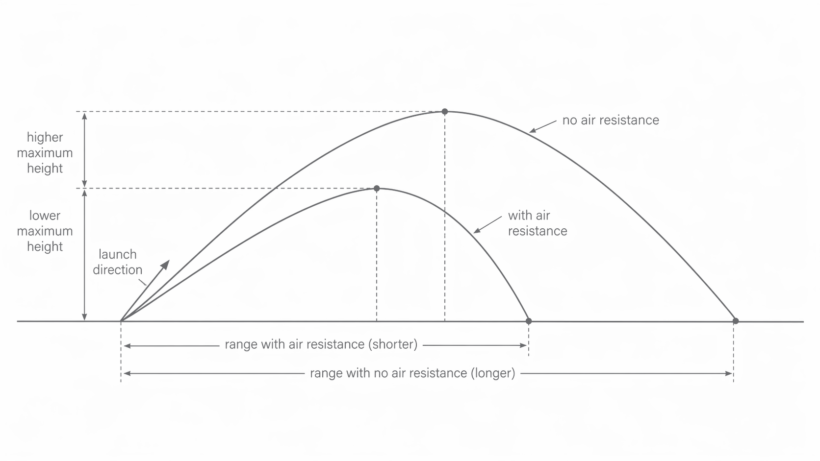
The main effects of air resistance on a projectile are:
- reduced range, because the horizontal speed falls continuously
- reduced maximum height, because drag opposes the upward motion during ascent
- an earlier peak, because the upward component of velocity is lost more quickly
- a steeper descent, because the projectile has lost horizontal speed by the time it falls
- loss of symmetry, so the path is no longer a neat parabola
Air resistance reduces both the height and the range of a projectile, and it makes the descent steeper than the ascent because the horizontal speed is no longer constant.
This is why real balls, arrows, and vehicles do not follow the perfectly symmetric paths predicted by the simplest model. The ideal model is still very useful, but you should always know what assumptions it depends on.