3.5.1.2 - Current-Voltage Characteristics
Current-voltage characteristics show how a component responds when the potential difference across it changes. By reading the shape of an I-V graph, you can tell whether a component has constant resistance, whether its resistance changes with temperature, or whether it allows current to flow much more easily in one direction than the other.
1. Ohm's Law and Ohmic Conductors
Ohm's Law
Ohm's law states that the current through a conductor is directly proportional to the potential difference across it, provided that physical conditions remain constant.
The important idea here is direct proportionality. If the potential difference doubles and the physical conditions do not change, the current also doubles. This is why an ohmic conductor has a constant resistance.
Ohmic Conductor
An ohmic conductor is a component for which current is directly proportional to potential difference when physical conditions, such as temperature, are kept constant.
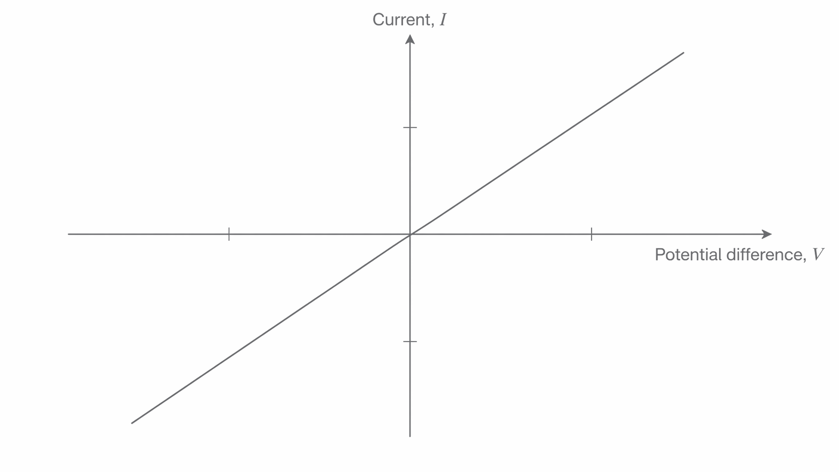
The equation is always the definition of resistance. Ohm's law is the special case where stays constant, so the I-V graph is a straight line through the origin.
Resistance Equation
The graph below shows this directly. Notice the straight line through the origin in both positive and negative quadrants, which tells you that current stays proportional to potential difference and the resistance stays constant. If current is on the vertical axis and potential difference is on the horizontal axis, the gradient is .
[DIAGRAM: asset_name: 5.1.2 - Current–Voltage Characteristics - Diagram 1; asset_slug: 5.1.2 - Current–Voltage Characteristics - Diagram 1; recommended_method: retained_png; description: I-V graph for an ohmic conductor with potential difference on the horizontal axis and current on the vertical axis. Show a straight line through the origin extending into positive and negative quadrants.]
2. Current-Voltage Characteristic of a Filament Lamp
A filament lamp is not an ohmic conductor because its temperature changes significantly as current increases. The filament gets hotter, and that changes the resistance.
When the metal filament heats up, the positive ions in the lattice vibrate more strongly. Conduction electrons collide with these vibrating ions more often, so it becomes harder for charge to move through the filament. The graph below shows this shape clearly, so notice how the curve is steep near the origin but becomes shallower as the lamp heats up and its resistance increases.
[DIAGRAM: asset_name: 5.1.2 - Current–Voltage Characteristics - Diagram 2; asset_slug: 5.1.2 - Current–Voltage Characteristics - Diagram 2; recommended_method: retained_png; description: I-V graph for a filament lamp. Show a curve through the origin that is symmetrical in positive and negative quadrants. Make the gradient steep near the origin and shallower at larger values of potential difference.]
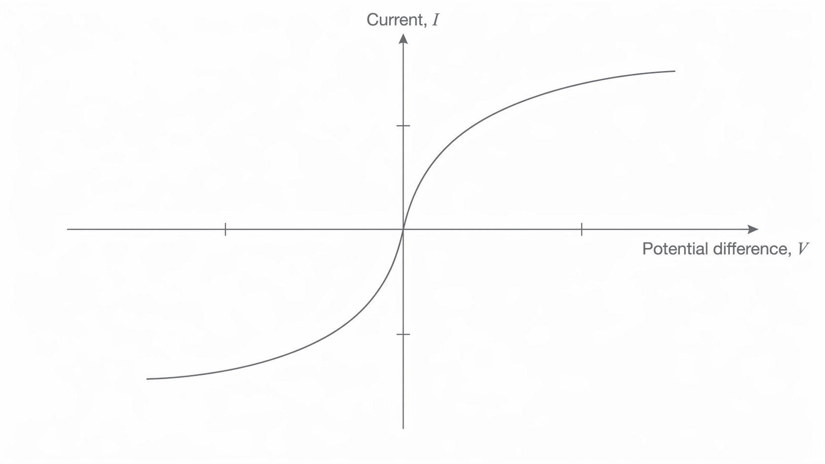
This is why the I-V graph curves. Near the origin, the filament is relatively cool, so the resistance is lower and the graph is steeper. At larger voltages, the filament becomes hotter, the resistance increases, and the gradient decreases. A decreasing gradient means that each extra volt produces a smaller increase in current.
3. Current-Voltage Characteristic of a Semiconductor Diode
Diode
A diode is a semiconductor component that allows current to flow easily in one direction but has a very high resistance in the opposite direction.
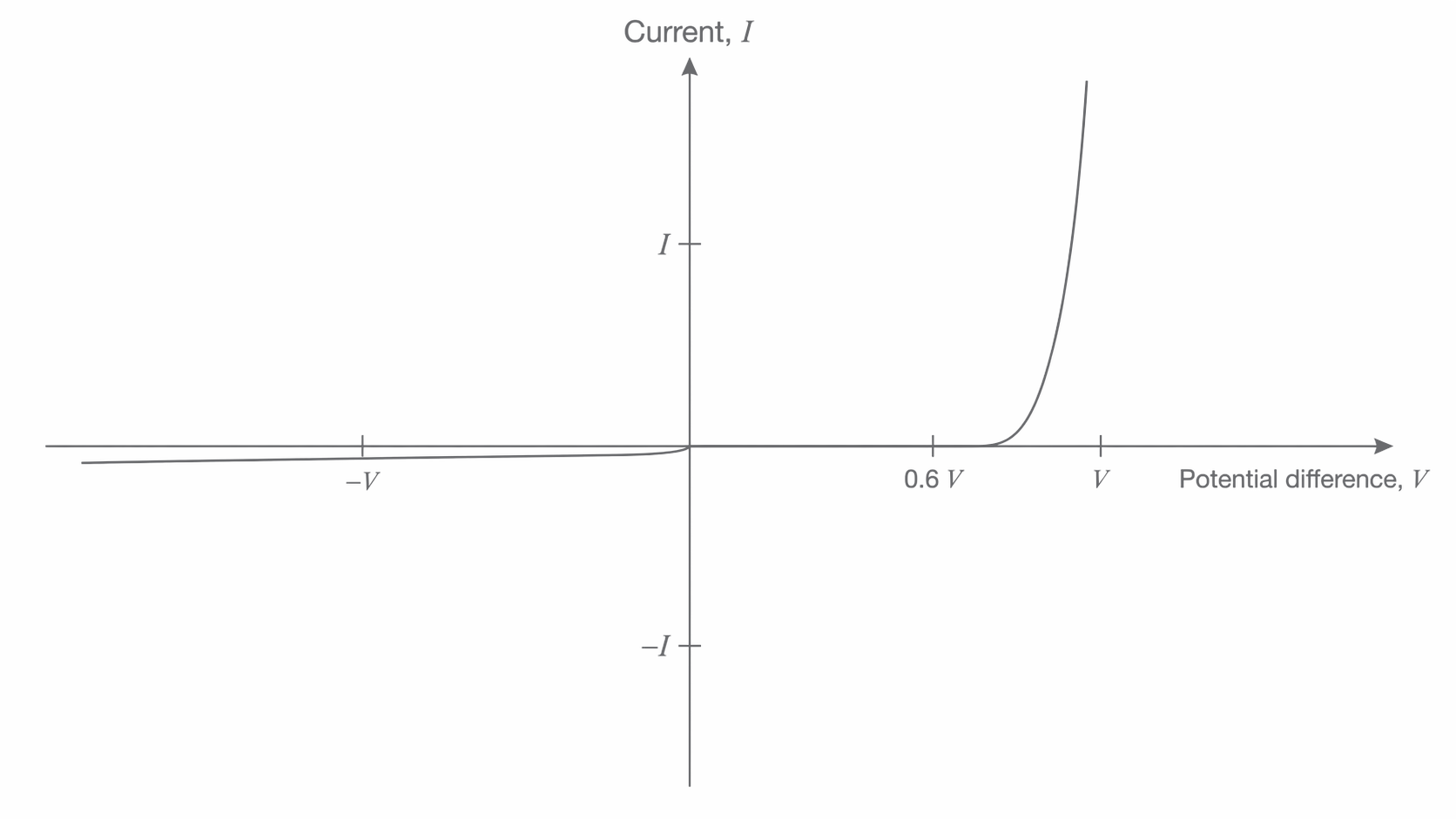
This means the diode has different behaviour in forward bias and reverse bias. Its I-V graph is therefore not symmetrical about the origin.
Threshold Voltage
The threshold voltage is the minimum forward potential difference needed before a diode conducts appreciably.
For a silicon diode, the threshold voltage is about 0.6 V. The graph below shows the key pattern to learn: notice the almost zero current in reverse bias and in forward bias below about 0.6 V, followed by the very steep rise once the threshold is reached.
[DIAGRAM: asset_name: 5.1.2 - Current–Voltage Characteristics - Diagram 3; asset_slug: 5.1.2 - Current–Voltage Characteristics - Diagram 3; recommended_method: retained_png; description: I-V graph for a silicon diode. Show almost no current in reverse bias, almost no current in forward bias until about 0.6 V, then a steep rise in current above 0.6 V.]
4. Comparing the Three Characteristics
The graph shape tells you what is happening to the resistance of the component.
| Component | Characteristic shape | What it means |
|---|---|---|
| Ohmic conductor | Straight line through the origin | Resistance is constant |
| Filament lamp | Symmetrical curve with decreasing gradient | Resistance increases as temperature rises |
| Semiconductor diode | Asymmetrical curve with a forward threshold and almost no reverse current | Resistance depends strongly on direction and applied voltage |
Questions can be drawn with either current or potential difference on the horizontal axis. Always look carefully at the axis labels before interpreting the gradient or identifying the component. For an ohmic conductor, you still get a straight line through the origin either way, but the gradient represents a different quantity depending on which variable is on which axis.
5. Ideal Ammeters and Voltmeters
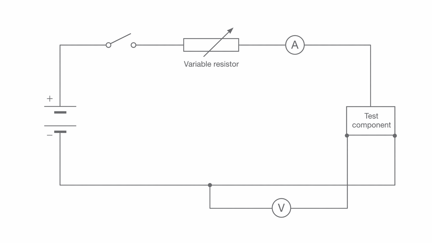
When measuring an I-V characteristic, the meters should affect the circuit as little as possible. That is why exam questions usually tell you to treat them as ideal unless stated otherwise.
Ideal Ammeter
An ideal ammeter has zero resistance, so it can be placed in series without changing the current in the circuit.
Because the ammeter is in series with the component, the same current passes through both the meter and the component.
Ideal Voltmeter
An ideal voltmeter has infinite resistance, so it is connected in parallel without drawing current from the circuit.
Because the voltmeter is connected across the component, it measures the potential difference across that component. The circuit below shows the standard arrangement, so notice that the ammeter is in series with the test component while the voltmeter is connected in parallel across it. If its resistance were not extremely large, it would draw current and change the circuit conditions.
[DIAGRAM: asset_name: 5.1.2 - Current–Voltage Characteristics - Diagram 4; asset_slug: 5.1.2 - Current–Voltage Characteristics - Diagram 4; recommended_method: retained_png; description: Circuit used to measure an I-V characteristic. Show a cell, variable resistor, switch, ammeter, and test component in series, with a voltmeter connected in parallel across the test component.]