3.3.1.2 - Longitudinal and Transverse Waves
Waves can be classified by how the oscillations are arranged relative to the direction of energy transfer. That single idea explains the difference between sound waves, electromagnetic waves, and waves on a string, and it also explains why polarisation is such strong evidence for the nature of transverse waves.
Part 1 — Longitudinal and Transverse Waves
The key comparison is between the direction of the oscillation and the direction in which energy is transferred. If the oscillation is at right angles to the direction of travel, the wave is transverse. If the oscillation is along the direction of travel, the wave is longitudinal.
Transverse Wave
A wave in which the oscillations are perpendicular to the direction of energy transfer.
Waves on a string are a clear mechanical example of a transverse wave. If the disturbance moves horizontally along the string, each part of the string moves up and down. Electromagnetic waves are also transverse, but in that case it is the electric and magnetic fields that oscillate.
Longitudinal Wave
A wave in which the oscillations are parallel to the direction of energy transfer.
Sound in air is the standard example of a longitudinal wave. The air particles oscillate back and forth along the line of travel, producing compressions and rarefactions.
In the figure, compare the direction of motion in each example: the string moves at right angles to the wave travel, while the air particles move parallel to it.
[DIAGRAM: asset_name: 3.1.2 - Longitudinal and Transverse Waves - Diagram 1; asset_slug: 3.1.2 - Longitudinal and Transverse Waves - Diagram 1; recommended_method: retained_png; description: Two labelled sketches. Left: a wave on a string travelling to the right with the string oscillating up and down, showing perpendicular motion. Right: a longitudinal wave in air with compressions and rarefactions travelling to the right, showing particle motion back and forth parallel to the wave direction.]
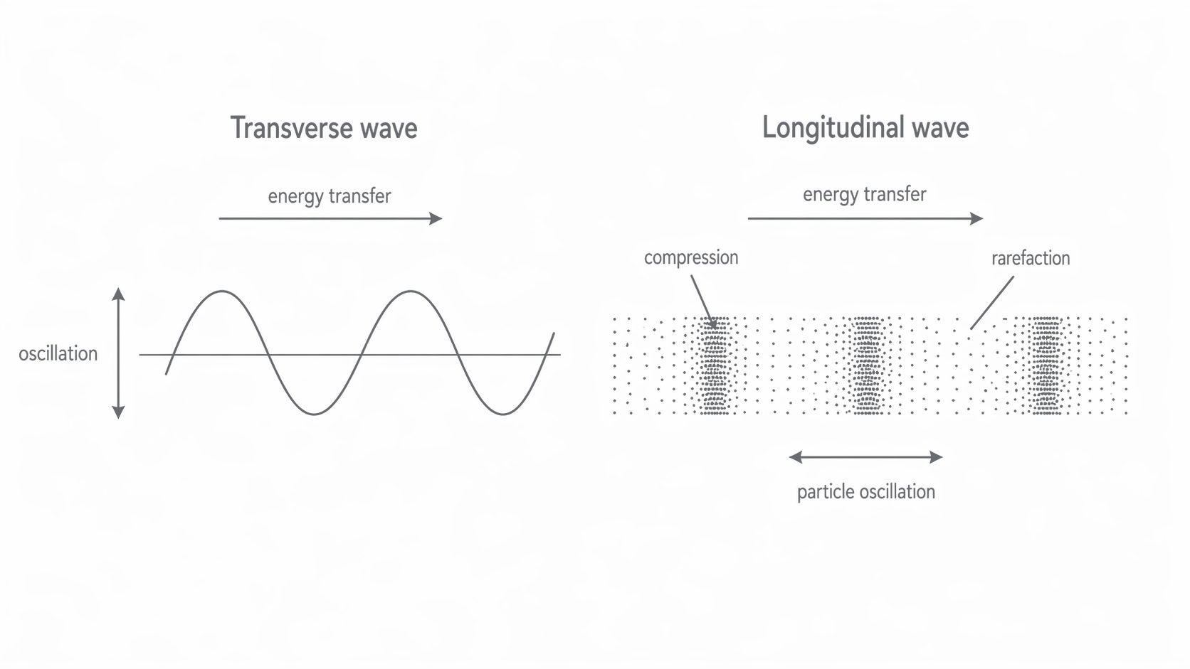
This perpendicular-versus-parallel distinction is the idea you should keep checking against every example in this topic.
Part 2 — Electromagnetic Waves in a Vacuum
All electromagnetic waves are transverse. Radio waves, microwaves, infrared, visible light, ultraviolet, X-rays, and gamma rays all travel at the same speed in a vacuum even though they have different frequencies and wavelengths.
Speed of Electromagnetic Waves in a Vacuum
In an electromagnetic wave, the electric field and magnetic field both oscillate perpendicular to the direction of propagation, and they are perpendicular to each other as well. That is why electromagnetic waves count as transverse waves.
The same wave equation still applies, so if you know the frequency you can calculate the wavelength, or vice versa.
Wave Equation
Here, is the wave speed in m s, is the frequency in Hz, and is the wavelength in m.
This constant wave speed in a vacuum is one of the defining features of the whole electromagnetic spectrum.
Part 3 — Polarisation as Evidence for Transverse Waves
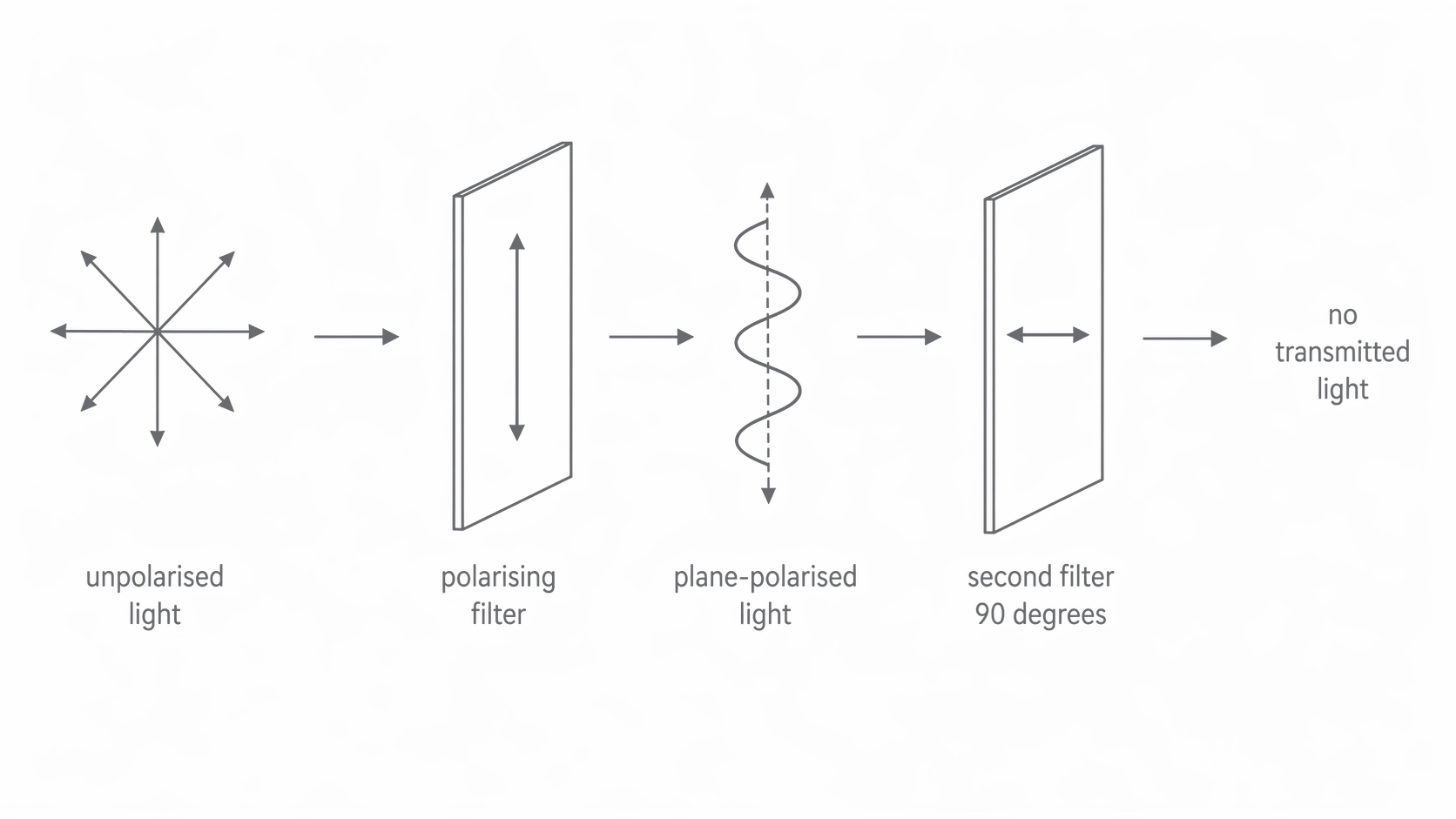
If the oscillations of a transverse wave are restricted to one plane, the wave is said to be plane-polarised. That restriction is only possible for a transverse wave, because a longitudinal wave has oscillations in just one line along the direction of travel.
Plane-Polarised Wave
A transverse wave in which the oscillations occur in one plane only.
You can picture this using a rope and a narrow slit. If the rope is being shaken in many planes, only the component of vibration aligned with the slit passes through. The emerging wave is then polarised. A second slit at right angles blocks the wave completely.
Light behaves in the same way with Polaroid material. For microwaves, a metal grille acts as a polariser: the electric-field component parallel to the wires causes electrons in the wires to move, so that component is absorbed or reflected, while the perpendicular component is transmitted. In every case, the ability to polarise the wave shows that the oscillations must be transverse.
In the figure, notice that the first filter selects a single plane of oscillation and the second, crossed filter blocks the transmitted wave completely.
[DIAGRAM: asset_name: 3.1.2 - Longitudinal and Transverse Waves - Diagram 2; asset_slug: 3.1.2 - Longitudinal and Transverse Waves - Diagram 2; recommended_method: retained_png; description: Unpolarised light approaching a polarising filter. After the filter, show plane-polarised light with one oscillation plane. Behind it, draw a second filter rotated by 90 degrees so no transmitted wave emerges.]
Because sound is longitudinal, it cannot be polarised. There is no choice of plane to select, only motion forwards and backwards along the direction of travel.
Part 4 — Polaroid Material and Aerial Alignment
One important application of polarisation is the use of Polaroid material to reduce glare. Reflected light from water, wet roads, or glass is often partially polarised, so a suitably oriented Polaroid filter can cut down the unwanted reflected component.
Polaroid sunglasses reduce glare by preferentially blocking the polarised component of reflected light. This makes it easier to see through reflections on water or to reduce the dazzling effect of sunlight reflected from wet roads.
Polarisation is also crucial in communication systems. A transmitting aerial produces plane-polarised radio waves, and the receiving aerial must be aligned in the same plane if it is to detect the largest possible signal.
For TV and radio transmission, the rods in the transmitting and receiving aerials are aligned to match the plane of polarisation of the radio wave. If a local transmitter uses horizontal polarisation, receivers are fitted with horizontal aerials; if it uses vertical polarisation, the receiving aerials must also be vertical.
This matching rule is the practical consequence of polarisation: the receiving system must be able to respond in the same plane as the oscillating field.
The same idea links every example in this lesson: the geometry of the oscillation determines both the wave classification and the way a device interacts with the wave.
If you can connect classification, polarisation, and aerial alignment in one explanation, then you have understood the core physics of this specification point.