3.5.1.4 - Circuits
Understanding how components combine in series and parallel is the foundation of all circuit analysis. In this lesson you will learn the rules that govern current and potential difference in DC circuits, how to calculate total resistance for series and parallel combinations, and how to apply the energy and power equations that describe energy transfer in electrical components. These ideas rest on two conservation laws -- conservation of charge and conservation of energy -- formalised as Kirchhoff's laws.
1. Current and Potential Difference Rules in DC Circuits
Before combining resistors or calculating power, you need to know how current and potential difference (pd) behave in series and parallel arrangements. These rules follow directly from two conservation principles.
Electric Current
Electric current is the rate of flow of charge. At any point in a circuit, the current is the charge passing that point per unit time.
Current rules
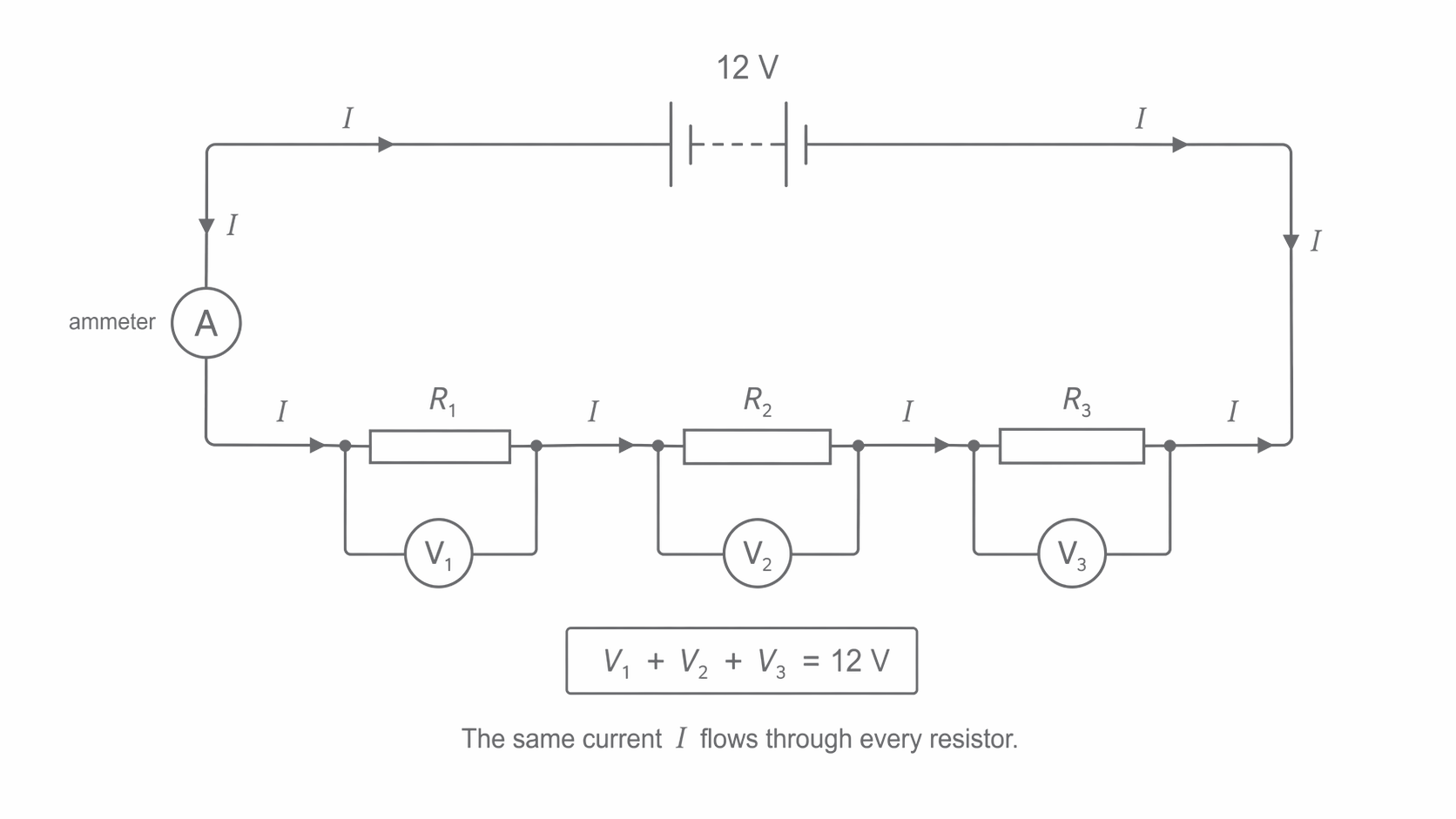
In a series circuit, the current is the same through every component. This is because charge cannot accumulate at any point -- the charge entering a component each second must equal the charge leaving it each second.
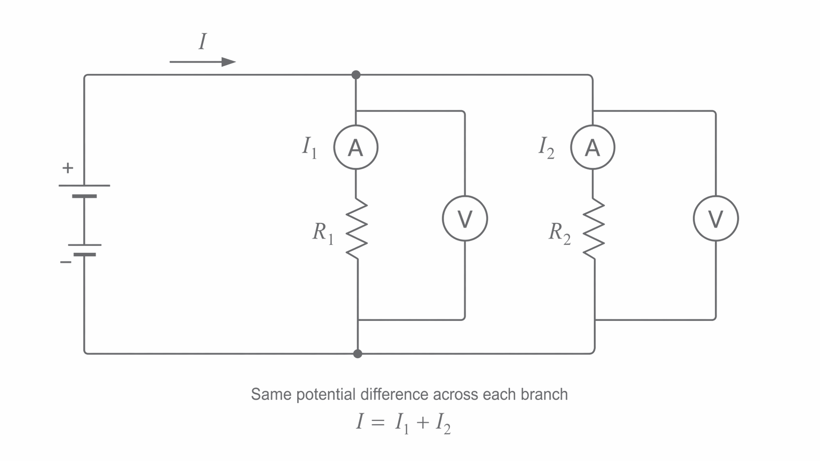
At a junction (parallel circuit), the total current entering the junction equals the total current leaving it. This is a direct consequence of conservation of charge -- charge is neither created nor destroyed.
Potential difference rules
Potential Difference
The potential difference between two points in a circuit is the energy transferred per coulomb of charge flowing between those points. It is measured in volts (V), where 1 V = 1 J C^{-1}.
For components in series, the total pd across the combination equals the sum of the individual pds:
This follows from conservation of energy: each coulomb of charge delivers some energy to each component, and the sum of these energy transfers equals the total energy supplied per coulomb by the source.
For components in parallel, the pd across each branch is the same. Every coulomb of charge that passes through any one of the parallel branches transfers the same amount of energy, regardless of which branch it takes.
The next figure focuses on a series circuit; notice that the same current passes through every resistor while the individual voltmeter readings add to the battery emf.
[DIAGRAM: asset_name: 5.1.4 - Circuits - Diagram 1; asset_slug: 5.1.4 - Circuits - Diagram 1; recommended_method: retained_png; description: A series circuit with a battery of emf 12 V and three resistors. Voltmeters across the resistors read V_1, V_2, V_3 such that V_1 + V_2 + V_3 = 12 V. A single ammeter shows the same current I through each resistor.]
The following figure shows the parallel case; notice that both branches share the same pd while the battery current splits into branch currents that add to the total.
[DIAGRAM: asset_name: 5.1.4 - Circuits - Diagram 2; asset_slug: 5.1.4 - Circuits - Diagram 2; recommended_method: retained_png; description: A parallel circuit with a battery. Two branches, each containing a resistor. Voltmeters across each branch read the same value V. Ammeters in each branch read I_1 and I_2. The total current from the battery is I = I_1 + I_2.]
2. Kirchhoff's Laws
The current and pd rules described above are formalised as Kirchhoff's two laws.
Kirchhoff's First Law (Junction Rule)
The total current entering a junction is equal to the total current leaving that junction. This is a statement of conservation of charge.
Mathematically, at any junction:
For example, if three wires meet at a junction and currents of 0.5 A and 1.0 A flow into the junction along two of the wires, the current flowing out along the third wire must be 1.5 A.
Kirchhoff's Second Law (Loop Rule)
For any closed loop in a circuit, the sum of the emfs around the loop is equal to the sum of the potential drops around the loop. This is a statement of conservation of energy.
Mathematically, for any loop:
Each time a charge carrier completes a loop, the energy it gains from sources of emf equals the energy it delivers to resistive components.
Kirchhoff's laws are used extensively in the design and analysis of printed circuit boards (PCBs) in electronic devices such as smartphones and computers. Engineers apply these laws to determine the current through and voltage across every component in circuits containing thousands of interconnected elements, ensuring each component operates within its rated limits.
3. Combining Resistors
Resistors in series
When resistors are connected in series, the same current passes through each one. The total pd across the combination is:
Dividing through by gives the total resistance:
Resistors in Series
where is the total resistance, and are the individual resistances, all measured in ohms (). This relationship is worth learning fluently because it lets you simplify any series section quickly.
The total resistance in series is always greater than any individual resistance, because each resistor adds to the opposition to current flow.
Resistors in parallel
When resistors are connected in parallel, the pd across each is the same. The total current is:
Since , dividing through by gives:
Resistors in Parallel
This relationship is worth remembering too. The total resistance of a parallel combination is always less than the smallest individual resistance, because providing additional paths for current reduces the overall opposition.
Useful shortcut for two resistors in parallel:
For example, a resistor in parallel with a resistor gives .
Combining series and parallel in one circuit
Many circuits contain both series and parallel sections. The strategy is to simplify from the inside out: first calculate the equivalent resistance of any parallel combination, then add that result in series with the remaining resistors.
Worked example: A circuit contains a resistor and a resistor in series with a parallel combination of a resistor and a resistor. Find the total resistance.
Step 1 -- Find the resistance of the parallel combination:
Step 2 -- Add in series:
4. Cells in Series and Parallel
Cells (batteries) can also be combined in series or parallel, and the rules follow from the same conservation principles.
Cells in series
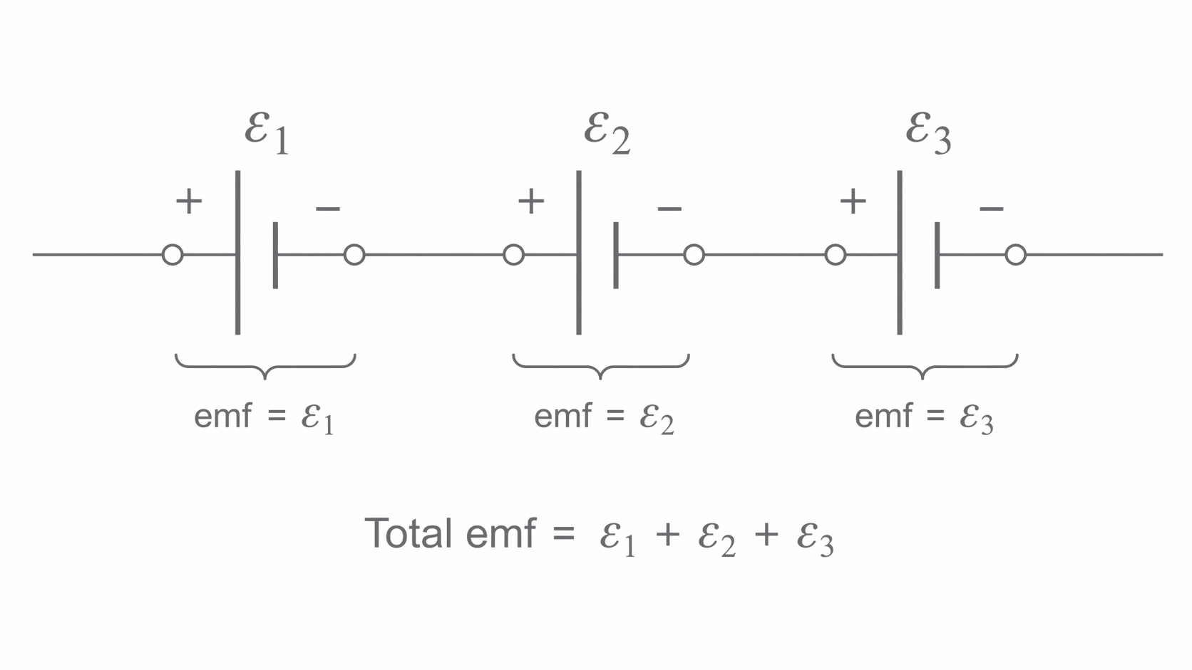
When cells are connected in series (positive terminal of one connected to the negative terminal of the next), the total emf is the sum of the individual emfs:
Cells in Series
If a cell is connected in reverse (opposing the others), its emf is subtracted. For example, if a 3.0 V cell and a 2.0 V cell are connected in series but opposing each other, the net emf is .
The figure below shows the orientation of cells in series; notice that each positive terminal connects to the next negative terminal so the emfs add around the chain.
[DIAGRAM: asset_name: 5.1.4 - Circuits - Diagram 3; asset_slug: 5.1.4 - Circuits - Diagram 3; recommended_method: retained_png; description: Three cells connected in series, each labelled with emf epsilon_1, epsilon_2, epsilon_3. The positive terminal of each connects to the negative terminal of the next. Total emf = epsilon_1 + epsilon_2 + epsilon_3.]
Identical cells in parallel
When identical cells, each of emf , are connected in parallel, the total emf remains equal to the emf of a single cell:
Identical Cells in Parallel
This is because the current splits equally between the cells, so each cell only needs to supply a fraction of the total current. Each charge carrier passes through only one cell, gaining energy per coulomb regardless of how many cells are in parallel. The advantage of connecting identical cells in parallel is that the effective internal resistance is reduced to (where is the internal resistance of one cell), allowing the combination to supply a larger current with less energy wasted internally.
Solar panels use both series and parallel cell combinations. Individual solar cells (each producing approximately 0.45 V) are connected in series to build up the required voltage. Multiple rows of series-connected cells are then connected in parallel to reduce the overall internal resistance and increase the current-delivering capacity of the panel.
Cells in series add their emfs. Identical cells in parallel maintain the same emf but reduce the effective internal resistance, allowing greater current delivery.
5. Energy and Power Equations
Energy transferred
When a charge moves through a potential difference , the energy transferred is . Since current , we can write , giving:
Energy Transferred
where is energy in joules (J), is current in amperes (A), is potential difference in volts (V), and is time in seconds (s).
Electrical power
Power is the rate of energy transfer. Dividing by :
Electrical Power
where is power in watts (W).
Substituting into gives two alternative forms:
Power Alternatives
These three forms (, , ) are all equivalent. Choose the form that uses the quantities you already know:
- Use when you know current and pd.
- Use when you know current and resistance (useful for series circuits where current is the common quantity).
- Use when you know pd and resistance (useful for parallel circuits where pd is the common quantity).
Resistance heating
The heating effect of current is caused by collisions between charge carriers (electrons) and the positive ions of the conducting material. Each collision transfers kinetic energy from the electron to the lattice, raising the temperature. The energy dissipated as heat per second is .
Worked example: A lamp has a power rating of 60 W and is connected to a 240 V supply. Find the current through the lamp and the energy transferred in 2 minutes.
Current:
Energy: (converting 2 minutes to 120 seconds).
Alternatively, .
Now let us bring together the resistor rules and the power equations in a more demanding problem.
6. Circuit Analysis Strategy
When tackling any DC circuit problem, follow a systematic approach:
- Identify which components are in series and which are in parallel.
- Simplify the circuit by replacing parallel combinations with their equivalent resistance, working from the innermost groups outward.
- Calculate the total resistance of the simplified circuit.
- Find the total current using (or for the full circuit).
- Work back outward to find the current through and pd across each individual component.
- Calculate power for individual components using whichever form of the power equation is most convenient.
Always check your answer: the pds around any complete loop must sum to the emf, and the currents entering any junction must sum to the currents leaving it.
Once you can do the arithmetic, the last check is whether the current-sharing idea feels intuitive.