3.3.2.2 - Diffraction
When light meets a narrow slit or a regularly spaced set of slits, it does not simply continue as one straight beam. It spreads, interferes with itself, and produces patterns that reveal wavelength and structure. In this lesson you will focus on the appearance of single-slit diffraction patterns, the grating equation at normal incidence, and why diffraction gratings are so useful in physics.
Part 1 - What Diffraction Means
Diffraction is a wave effect, so light shows it just as sound and water waves do. The spreading is most noticeable when the size of the gap or obstacle is similar to the wavelength of the wave. If the gap is much wider than the wavelength, the wave still travels mostly straight ahead and the diffraction is much less obvious.
Diffraction
Diffraction is the spreading out of waves as they pass through a gap or around an obstacle.
For visible light, the wavelength is very small, so a wide opening produces very little spreading. A narrow slit produces much more. This is why single-slit diffraction becomes easier to observe as the slit is reduced in width.
Part 2 - Single-Slit Diffraction Patterns
With monochromatic light, a single narrow slit produces a broad bright central maximum with weaker bright fringes on either side. These outer fringes are separated by dark regions where destructive interference occurs. The central maximum is much brighter than the others and is twice the width of each outer bright fringe. The outer bright fringes have equal width, but their intensity decreases with distance from the centre.
The figure below shows the pattern you are expected to recognise; notice the broad central maximum, the narrower outer bright fringes, and the way the intensity falls away from the centre.
[DIAGRAM: asset_name: 3.2.2 - Diffraction - Diagram 1; asset_slug: 3.2.2 - Diffraction - Diagram 1; recommended_method: retained_png; description: A narrow single slit illuminated by monochromatic light. A distant screen shows a broad central bright maximum, then alternating dark and bright fringes of decreasing brightness on both sides. The central maximum is labelled as twice the width of each outer bright fringe.]
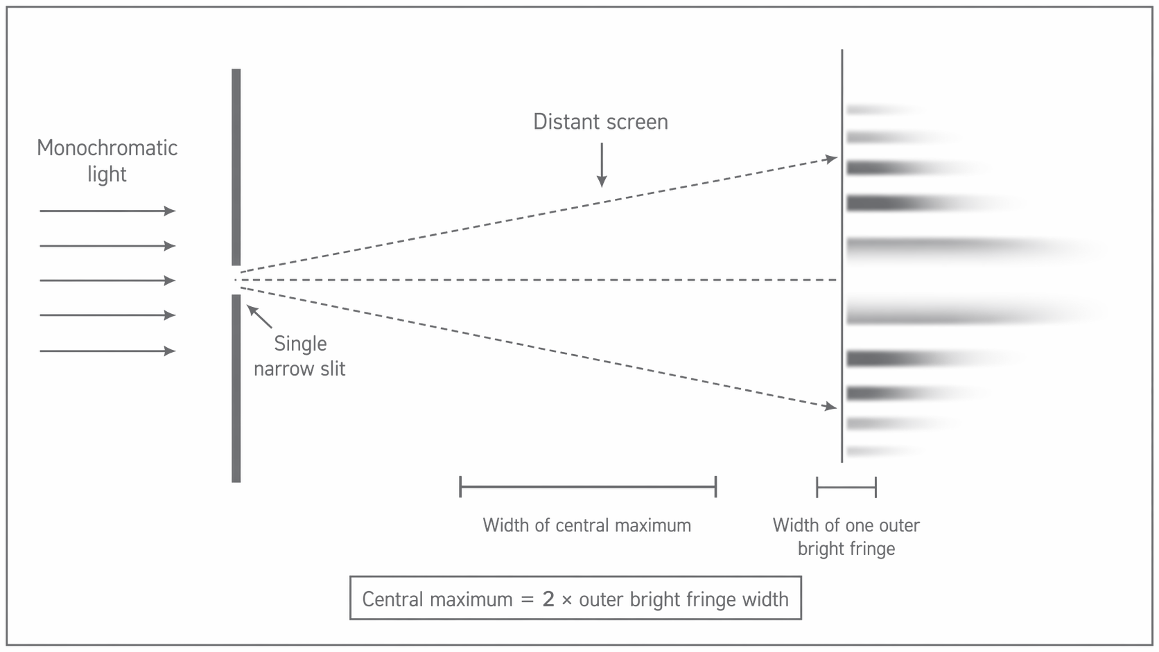
For this specification, you need the appearance of the pattern and the qualitative changes in its width. You do not need an intensity-against-angle graph.
If white light is used instead, each wavelength diffracts by a slightly different amount. The central maximum is white because all wavelengths overlap there. On each side of the centre, the fringes are coloured spectra: violet is closest to the central maximum and red is furthest away.
The width of the central maximum changes in a simple qualitative way:
- a longer wavelength gives a wider central maximum
- a narrower slit gives a wider central maximum
Part 3 - Diffraction Gratings
A diffraction grating contains a very large number of equally spaced parallel slits. Light is incident normally on the grating, and each slit diffracts the light that passes through it. The diffracted waves from adjacent slits only reinforce strongly in certain directions, so the transmitted light appears as a series of sharp maxima.
Diffraction Grating
A diffraction grating is a plate or film containing many equally spaced parallel slits.
The central beam is the zero order maximum, where the light continues straight through. Maxima on either side are called first order, second order, and so on. Because a grating has many slits, the bright maxima are much sharper than those from a double-slit arrangement, which makes their angles easier to measure accurately.
A longer wavelength is diffracted to a larger angle for the same grating and the same order. A grating with smaller slit spacing also gives larger diffraction angles.
Part 4 - Deriving the Grating Equation
To derive the diffraction grating equation, consider two neighbouring slits separated by a distance . Look at rays from these two slits travelling to the same bright maximum at an angle to the normal.
The figure below sets up the geometry for the derivation; notice that the extra path length is opposite the angle while the slit spacing forms the hypotenuse of the right-angled triangle.
[DIAGRAM: asset_name: 3.2.2 - Diffraction - Diagram 2; asset_slug: 3.2.2 - Diffraction - Diagram 2; recommended_method: retained_png; description: Two adjacent slits in a diffraction grating, separated by distance d. Rays from the slits travel at angle theta to the normal. The lower ray travels an extra distance labelled n lambda. A right-angled triangle shows that the extra path is opposite angle theta and the slit spacing d is the hypotenuse.]
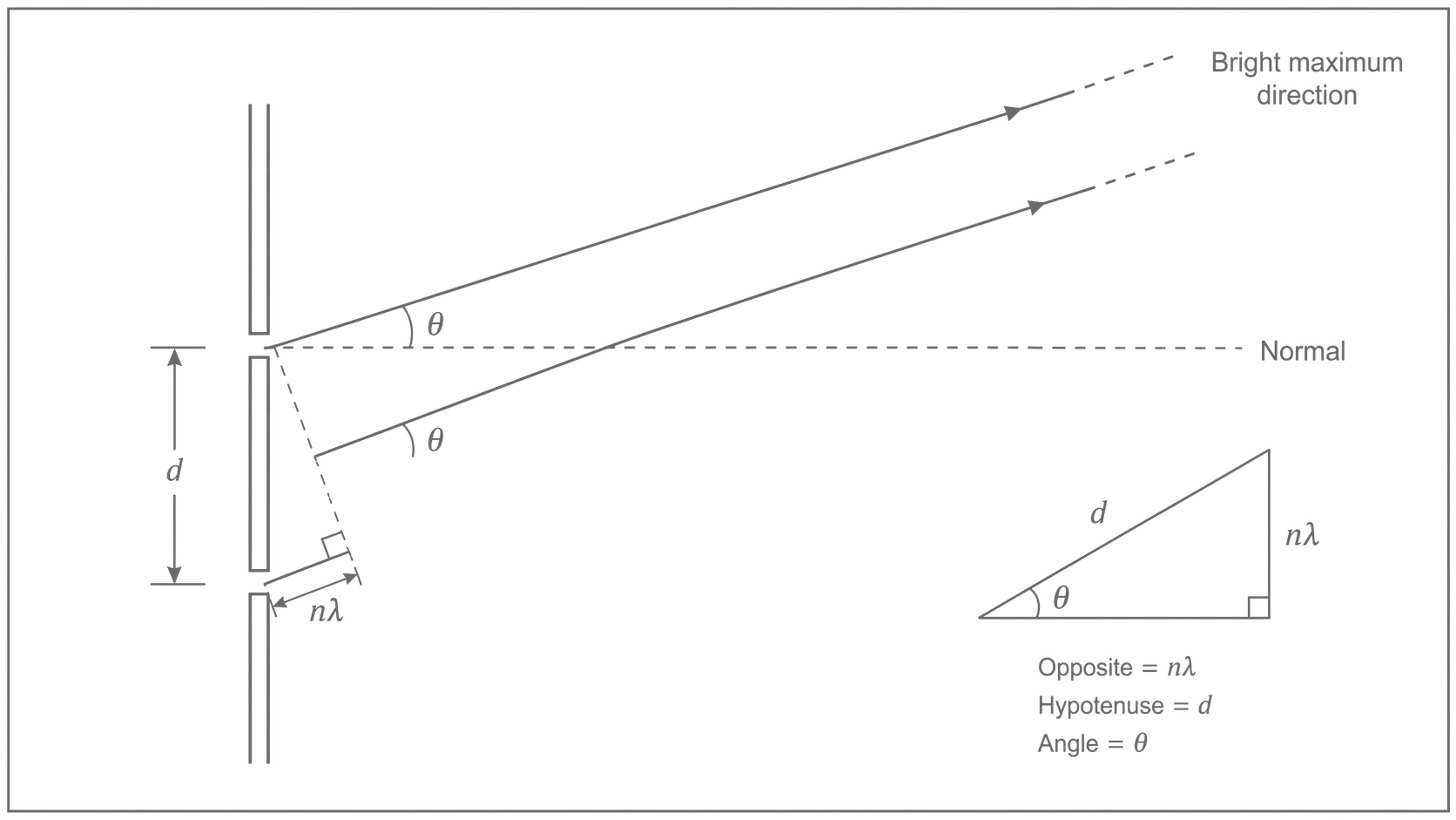
For a maximum to form, the waves from adjacent slits must arrive in phase. That happens when their path difference is a whole number of wavelengths:
- first order maximum: path difference =
- second order maximum: path difference =
- nth order maximum: path difference =
From the right-angled triangle in the diagram,
So for the nth order maximum,
Rearranging gives the required result.
Diffraction Grating Equation
Here, is the slit spacing, is the angle from the normal, is the order number, and is the wavelength. If a grating is labelled by the number of lines per metre , then the slit spacing is .
The highest possible order is found by using the fact that can never be greater than 1. This means the greatest possible value of is the whole-number part of .
The calculation above shows two important ideas at once. Higher orders appear at larger angles, and there is always a limit because cannot exceed 1.
Part 5 - Applications of Diffraction Gratings
Diffraction gratings are useful because they separate different wavelengths very clearly. That lets physicists identify substances and measure very small spacings.
Starlight can be passed through a diffraction grating to produce a spectrum. Dark absorption lines appear at specific wavelengths, and those wavelengths reveal which elements are present in the star's atmosphere.
This is why gratings are central to spectroscopy. A sharp pattern makes it easier to distinguish wavelengths that are close together.
In X-ray crystallography, the regular spacing between atoms in a crystal acts like a natural diffraction grating for X-rays. By analysing the diffraction pattern, physicists can determine atomic spacing and infer the structure of the crystal.
The same wave idea runs through both applications: diffraction is strongest when the spacing in the structure is comparable to the wavelength being used.
For this specification, remember the appearance of the single-slit pattern, how its central maximum changes with wavelength and slit width, the derivation of , and how gratings are used to analyse wavelengths.