82-85 - Polarisation and Diffraction (CP8)
This lesson is about a quiet but powerful idea: the direction a wave vibrates, and the way a wavefront spreads, can be used to measure something far too small to place a ruler against. By the end, the pattern of bright spots from a diffraction grating should feel less like a mysterious wall display and more like a wavelength-measuring machine.
Plane Polarisation
Light is a transverse electromagnetic wave. Its electric field vibrates at right angles to the direction in which the wave travels. If light travels forwards along a bench, the electric field might vibrate up-down, left-right, or at any angle sideways to the beam.
Unpolarised light is not one neat sideways vibration. It is a mixture of waves whose electric fields vibrate in many different sideways directions.
Plane polarised wave
A transverse wave whose oscillations are confined to one plane containing the direction of travel; for light, the electric field oscillates in one fixed direction.
A polarising filter helps make the idea physical. It transmits the component of the electric field along its transmission axis and absorbs the perpendicular component. If unpolarised light passes through one polariser, the transmitted light is plane polarised. If a second polariser, called an analyser, is turned so that its axis is parallel to the first, the light passes through. If the analyser is turned through , the transmitted intensity becomes very small because the selected vibration direction is blocked.
Misconception contrast: plane polarisation does not mean the light travels in a flat sheet. The wave still travels along the beam. It means the vibration direction of the electric field is restricted to one plane.
This also explains why polarisation is evidence that light is transverse. A longitudinal wave in air, such as ordinary sound, vibrates along its direction of travel, so there is no sideways vibration direction for a polariser to select.
For Edexcel, state what is meant by plane polarisation needs the idea of vibrations in one plane. If the answer says only "light has been filtered", it names a method but not the physics.
Diffraction Using Huygens' Construction
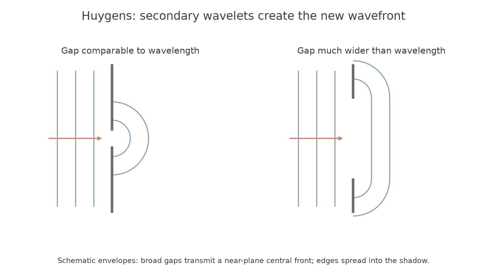
A wavefront spreads when part of it is blocked by an aperture or obstacle.
[DIAGRAM: asset_name: huygens gap wavefronts; asset_slug: 9ph0_huygens; recommended_method: matplotlib; description: Schematic same-wavelength incident plane fronts and curved transmitted envelopes for narrow and broad gaps; edge diffraction retained.]
Diffraction
The spreading of a wave when it passes through a gap or around the edge of an obstacle; pronounced when the gap is comparable to or smaller than the wavelength.
Diffraction is not the same as refraction: refraction needs a change of medium and usually a change of wave speed. Diffraction can happen in the same medium simply because a wavefront is interrupted.
Huygens' construction gives a way to predict the spreading:
- Treat every point on a wavefront as a source of small secondary wavelets.
- After a short time, the new wavefront is the smooth envelope touching those wavelets.
Now imagine a plane water wave reaching a gap.
If the gap is much wider than the wavelength, most of the wavefront keeps moving straight on. The edges spread a little because the points near the edges produce wavelets with room to spread sideways.
If the gap is comparable in size to the wavelength, the opening restricts the exposed wavefront. The secondary wavelets spread sideways and their envelope is strongly curved, so the wave spreads strongly after the gap.
The same reasoning works around an obstacle. The points on the wavefront near the edges of the obstacle produce wavelets that spread into the region behind it, so the wave bends into what a ray model would have called the shadow region.
Misconception contrast: diffraction is not the wave "squeezing through" and then deciding to spread. The spreading is already contained in Huygens' construction: each exposed point of the wavefront sends out wavelets.
For an explain question, do not stop at "waves spread out". Link the spreading to wavelets from the wavefront and to the size of the gap or obstacle compared with the wavelength.
The Diffraction Grating Equation
A diffraction grating has many equally spaced slits or lines. Each slit diffracts the incident light, so light from many slits overlaps. In certain directions the waves from neighbouring slits arrive in phase and reinforce each other, making a bright maximum.
For normally incident light, the path difference between light from neighbouring slits, for a direction at angle to the straight-through beam, is:
Bright maxima occur when this path difference is a whole number of wavelengths:
Diffraction grating
| Symbol | Meaning | Unit |
|---|---|---|
| order number of the maximum: 0, 1, 2, … | no unit | |
| wavelength of the light | m | |
| spacing between adjacent lines (reciprocal of lines per metre) | m | |
| angle from the central maximum to the th-order maximum | ° |
For light incident normally on the grating.
The central maximum is , so for all wavelengths. It is useful for measuring positions, but it does not let you calculate using division by .
The main symbol trap is . A grating labelled does not have . The line density is the number of slits per distance. The spacing is the reciprocal:
Worked example:
A red laser is shone normally through a diffraction grating labelled . The first-order maximum is observed at from the central maximum. Calculate the wavelength.
Decision point 1: What is ?
First order means . It does not mean .
Decision point 2: What is ?
The grating spacing is:
Decision point 3: Which angle goes into the equation?
Use the angle from the central maximum to the first-order maximum, so .
Now substitute:
That is , because .
Guided check:
If a grating gives a second-order maximum at about , then:
and
The division by is there because the maximum is second order. Forgetting that would double the wavelength.
Core Practical 8 Method
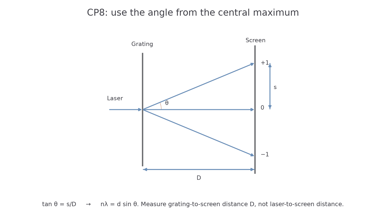
Core Practical 8 determines the wavelength of light from a laser or other light source using a diffraction grating. The clever move is to measure large distances on a wall or screen, then use trigonometry to find the tiny wavelength.
[DIAGRAM: asset_name: grating practical geometry; asset_slug: 9ph0_grating_geometry; recommended_method: matplotlib; description: Normally incident laser, grating, perpendicular screen, central and first-order maxima with distances s and D and diffraction angle.]
Continue this lesson.
You’re previewing NovaLearn without an account. Create a free account to read the rest.
Create free account