23-24 - Moments, Centre of Gravity and Equilibrium
Moments, centre of gravity and the principle of moments for a body in equilibrium. You will treat turning effects as measurable quantities so balanced objects can be analysed rather than guessed.
The turning effect of a force
Push a door close to the hinge and it barely turns. Push with the same force at the handle and it turns easily. The force has not changed; the distance of its line of action from the hinge has changed.
Moment of a force
The turning effect of a force about a point: the force multiplied by the perpendicular distance from the point to the force's line of action.
Moment of a force
: force (N); : perpendicular distance from the axis of rotation to the line of action of the force (m). Moment in N m.
The line of action is the straight line in the direction of the force, extended through the object. The distance is not automatically the length of the handle, beam or rod. It is the shortest distance from the pivot to that line.
In two-dimensional equilibrium questions, treat moments as clockwise or anticlockwise about a chosen pivot. A common sign choice is clockwise positive and anticlockwise negative, but it is just as valid to keep the two totals separate and equate them when the body is balanced.
Misconception contrast: a moment has the same base units as energy, but it is not energy. Write the unit as , not , because a moment describes a turning effect about a point.
For the command word state what is meant by, a full answer needs the perpendicular distance idea. "Force times distance" is too loose because it does not say which distance.
Choosing the perpendicular distance
The hardest part of is often not the multiplication. It is choosing .
Imagine tightening a nut with a spanner. The pivot is the centre of the nut. A force of is applied at the end of a spanner, but the force is at to the spanner rather than exactly at right angles.
Worked example: calculate the moment about the nut.
Decision point 1: What is the pivot?
The nut is the axis of rotation.
Decision point 2: Can be ?
No. The length is the distance along the spanner. The equation needs the perpendicular distance from the nut to the force's line of action.
Decision point 3: How do we find the perpendicular distance?
The force makes an angle of to the spanner, so:
Now use the moment equation:
The moment is smaller than it would be for a perpendicular push. If the same force were at right angles, the perpendicular distance would be the full , so the moment would be .
Equivalent route: you may instead find the component of the force perpendicular to the spanner, , then multiply by . Both routes are the same physics. Edexcel's wording makes the perpendicular distance route especially clean.
The principle of moments
A body in static equilibrium is not accelerating and not rotating. For this lesson, the key rotational condition is:
Principle of moments
For a body in equilibrium, the sum of the clockwise moments about any point equals the sum of the anticlockwise moments about that point.
The pivot force often does not appear in the moment equation if you take moments about the pivot, because its perpendicular distance from that pivot is zero. This is why choosing a pivot is a powerful decision, not just a drawing habit.
Worked example: a light beam of negligible weight balances on a pivot. A downward force acts to the left of the pivot. A second downward force of acts to the right of the pivot. How far from the pivot should the force be placed?
Moment from the left force:
For balance, the right-hand force must produce an equal moment in the opposite turning direction:
So the force should be from the pivot.
Misconception contrast: "the larger force must be farther away" is the wrong instinct. For equal turning effect, a larger force needs a smaller perpendicular distance.
For “calculate”, show the moment equation, substitution and unit. For “determine”, make the quantitative route visible: the examiner must see how the distance or force follows from the balance condition.
Extended bodies and centre of gravity
An extended body has size, so its weight is spread throughout the body. For moment calculations in a uniform gravitational field, you can replace that distributed weight by a single weight acting at the centre of gravity.
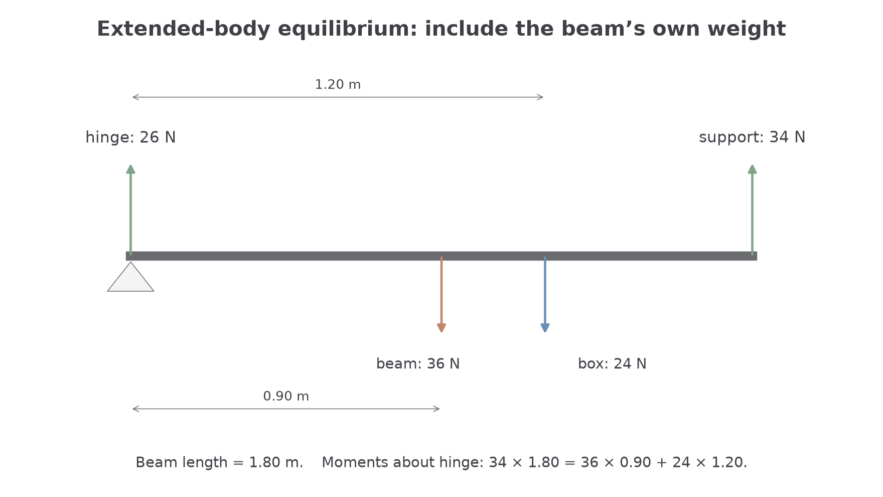
[DIAGRAM: asset_name: Beam equilibrium with its own weight; asset_slug: 9ph0_beam_equilibrium; recommended_method: deterministic; description: Uniform 1.80 m beam with 36 N weight at 0.90 m and 24 N load at 1.20 m. Right support 34 N and hinge 26 N satisfy moments and vertical force balance.]
Centre of gravity
The single point through which the whole weight of a body can be taken to act.
For a uniform, regular object, the centre of gravity is at its geometric centre. For a non-uniform object, or for an object with an added load, it shifts toward the heavier side.
Misconception contrast: the centre of gravity is not "where the object is supported". A support can be anywhere. The centre of gravity is where the object's weight can be treated as acting.
Worked example: a uniform horizontal beam is long and has a weight of . It is hinged at the left end. A vertical support at the right end pushes upward on the beam. A box of weight rests from the hinge. Determine the upward force from the right-hand support.
Decision point 1: Which pivot makes the algebra simplest?
Take moments about the hinge. The unknown hinge force acts at the hinge, so its moment about the hinge is zero.
Decision point 2: Where does the beam's own weight act?
The beam is uniform, so its weight acts at its centre of gravity, halfway along the beam:
Moment table about the hinge:
| Force | Distance from hinge | Turning effect |
|---|---|---|
| right support upward | anticlockwise | |
| beam weight downward | clockwise | |
| box weight downward | clockwise |
Apply the principle of moments:
If a later part of a question asked for the hinge force, you would then use vertical force equilibrium. But the moment calculation itself was made simpler by choosing the hinge as the pivot.
Locating a centre of gravity
If an object balances on a narrow support, the vertical line through its centre of gravity passes through the support. If the centre of gravity is to one side of the support, the object's weight has a moment and the object tips.
A simple practical method for a rod or metre rule is:
- Place the rod on a knife-edge or narrow pivot.
- Move it until it just balances horizontally.
- Mark and measure the balance position.
- Repeat by approaching balance from both sides and take a mean.
The measurement uncertainty is not just the ruler's scale. There is also judgement in deciding when the rod is exactly horizontal. Repeats reduce the effect of random variation in that judgement. They do not remove a systematic error such as a badly positioned zero mark or a pivot that is not actually narrow.
For a loaded metre rule, a balance position is also the combined centre of gravity.
Worked example: a uniform metre rule has weight , acting at the mark. A small object of weight is attached at the mark. Find the balance position measured from the end.
Use a moment-style data table:
| Weight | Position from left end |
|---|---|
| total | unknown balance position |
The total moment of the separate weights about the left end is equal to the moment of the total weight acting at the combined centre of gravity:
The balance point is about from the left end. That is closer to the added object than to the middle of the rule.
If a question gives masses instead of weights, convert to weights with when an actual moment is required. In a balance-position ratio where every force is a weight, the common factor may cancel, but do not leave final force moments in .
Force Balance and Support Reactions
Rotational equilibrium and force equilibrium are separate conditions. Two equal opposite forces on different parallel lines can have zero resultant force and still turn a body. Therefore a stationary beam needs both zero resultant force and zero resultant moment.
After a moment equation gives one support force, use the vertical force equation to find the other. In the 1.80 m beam example, the total downward force is . The right support supplies 34 N, so the hinge supplies upward. Both conditions are now satisfied.
If the box moves towards the right support, its clockwise moment about the hinge increases while the right support’s moment arm is fixed. The right support force increases and the left support force decreases because their sum remains 60 N. The beam’s own weight still acts at its midpoint; moving the box shifts only the combined centre of gravity.
A simple contact support can push but cannot pull. If a calculated contact reaction becomes negative, the assumed supported arrangement cannot remain in that equilibrium: contact is lost and tipping may begin. A hinge or secured cable has different constraints, so identify the support model before interpreting a sign.
A body is in equilibrium only when both the resultant force and the resultant moment are zero. Taking moments about an unknown force's point of action removes that force from the equation.