3.14-3.17 - Reflection, refraction and ray diagrams
Light travels as a transverse wave, and ray diagrams give a clean way to show the direction in which light energy travels. In this lesson, the important skill is to use a normal line and straight ray lines accurately, so that reflection and refraction are described by the geometry of the diagram. The practical work then turns those ray diagrams into measured evidence using transparent blocks.
Light rays and normals
Light waves are transverse waves. That means the oscillations are perpendicular to the direction in which the wave transfers energy.
Transverse wave
A transverse wave has oscillations at right angles to the direction of energy transfer.
In ray diagrams, a ray is a straight line with an arrow showing the direction in which light travels. The ray is a model; it is not a thin piece of light by itself. It helps you predict the path of light at a boundary.
When light meets a boundary, two important changes of direction can happen:
- reflection, where light bounces off the boundary
- refraction, where light changes direction as it passes from one material into another
The most useful construction line is the normal. The normal is drawn at 90 degrees to the surface at the exact point where the ray meets the surface. Angles in reflection and refraction diagrams are measured from the normal, not from the surface.
Law of reflection
Reflection from a plane mirror follows a simple rule: the angle of incidence equals the angle of reflection.
[DIAGRAM: asset_name: Reflection, refraction and ray diagrams - diagram 01; asset_slug: p28_reflection_refraction_and_ray_diagrams__diagram_01; recommended_method: image_gen; description: Monochrome ray diagram for the law of reflection at a plane mirror. Show a plane mirror, a dashed normal, an incident ray, a reflected ray, angle labels i and r measured from the normal, and the statement i = r.]
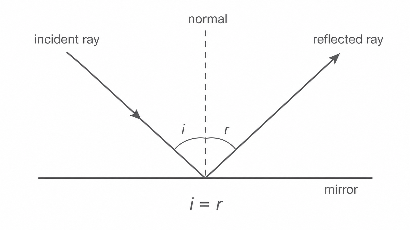
The angle of incidence is the angle between the incident ray and the normal. The angle of reflection is the angle between the reflected ray and the normal.
If the incident ray makes an angle of 35 degrees with the normal, the reflected ray also makes an angle of 35 degrees with the normal. The two rays are on opposite sides of the normal, so a correct diagram looks symmetrical about the normal.
Be careful with angle wording. If a question says the ray is 20 degrees to the mirror surface, that is not the angle of incidence. The normal is 90 degrees to the surface, so the angle to the normal is 70 degrees.
Refraction at boundaries
Refraction happens when light passes from one material into another and changes speed. If the ray hits the boundary at an angle to the normal, this speed change makes the ray change direction.
Refraction
Refraction occurs as a wave passes between materials where its speed differs. It changes direction at oblique incidence; at normal incidence its direction stays the same.
A common school example is light travelling from air into glass. Light travels more slowly in glass than in air, so the ray bends towards the normal when it enters the glass. When the ray leaves glass and enters air, it speeds up and bends away from the normal.
As in reflection, the angle of incidence is measured between the incident ray and the normal. The angle of refraction is the angle between the refracted ray and the normal.
[DIAGRAM: asset_name: Reflection, refraction and ray diagrams - diagram 02; asset_slug: p28_reflection_refraction_and_ray_diagrams__diagram_02; recommended_method: image_gen; description: NovaLearn pale-palette rectangular glass-block ray diagram with 40° incidence, 25° refraction and 40° emergence measured from perpendicular normals; arrows, i/r arcs and towards/away-from-normal labels show a laterally displaced parallel emergent ray.]
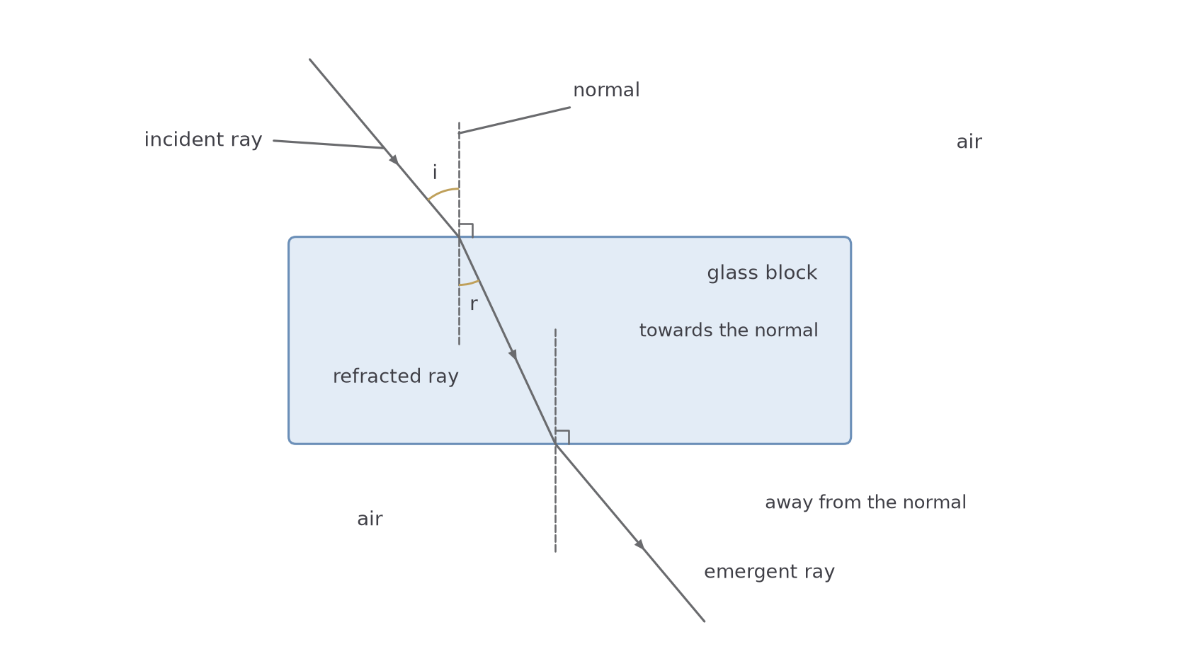
For a rectangular glass block, the entry face and exit face are parallel. With air on both sides and entry and exit through these parallel faces, the bending away from the normal at the exit face exactly undoes the bending towards the normal at the entry face, so the emergent ray is parallel to the incident ray. At oblique incidence it is shifted sideways. The shift is called lateral displacement. You do not need to calculate it in this lesson; you only need to recognise and draw the path.
If a ray travels along the normal, it can change speed but it does not change direction, because there is no sideways angle to bend towards or away from.
Continue this lesson.
You’re previewing NovaLearn without an account. Create a free account to read the rest.
Create free account