4.2.2b - Parallel Circuits and Circuit Calculations
Parallel circuits give electric charge more than one route through a circuit. That changes how potential difference, current and resistance behave, so the first job in any circuit question is to recognise the connections before doing any arithmetic. In this lesson, you will use parallel-circuit rules, simple current-potential difference-resistance calculations, and practical circuit-checking ideas.
Recognising parallel paths
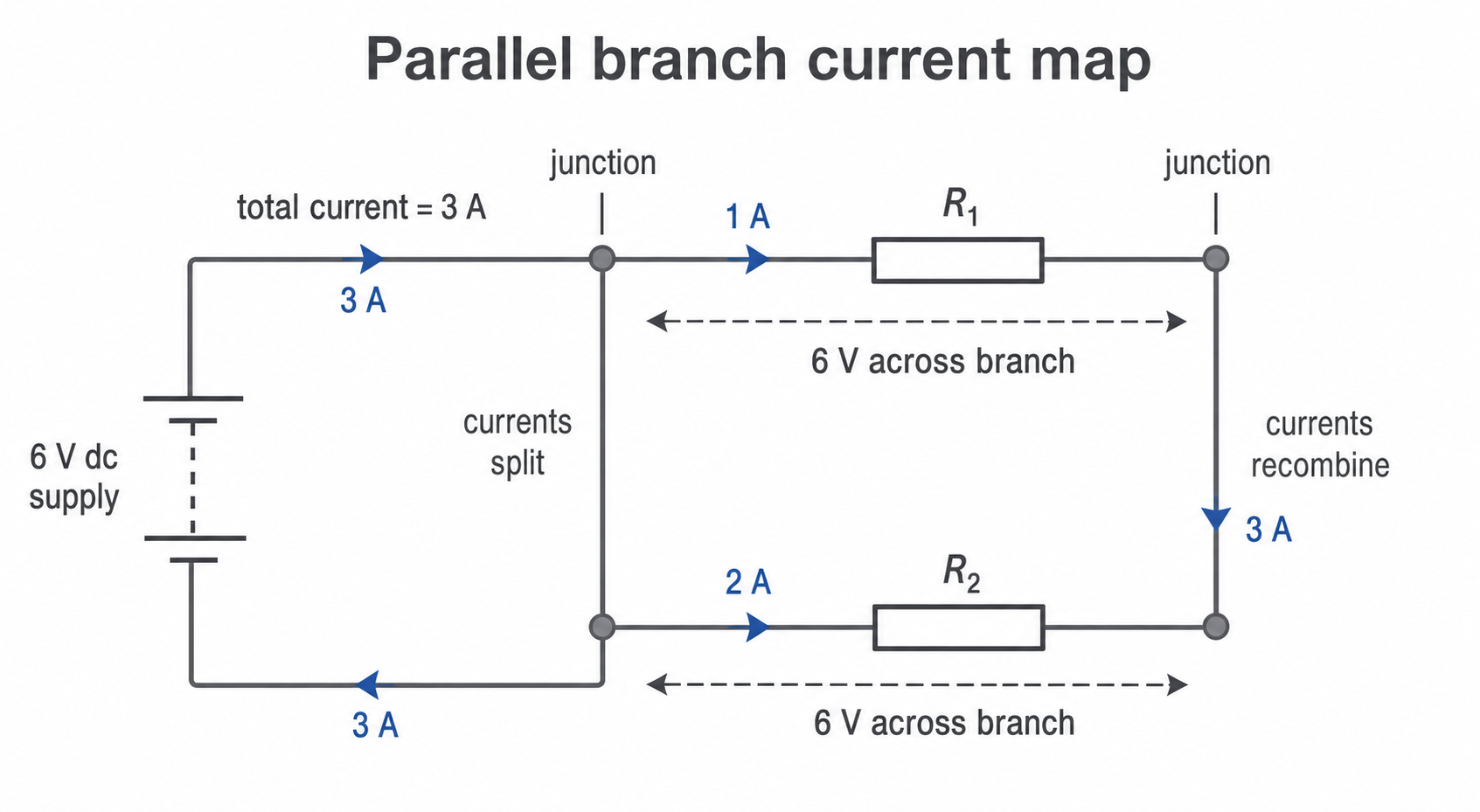
In a series circuit, components are connected one after another in a single loop. In a parallel circuit, components are connected on separate branches between the same two junctions. Charge can split at one junction, travel through different branches, then join again at the other junction.
Branch
A branch is one possible path for current between two junctions in a parallel part of a circuit.
Look for junctions first. If two components have both ends connected to the same pair of junctions, they are in parallel with each other. If there is only one route through the components, they are in series.
[DIAGRAM: asset_name: Parallel branch current map - diagram 1; asset_slug: 021_4_2_2b_parallel_circuits_and_circuit_calculations_diagram1; file: diagram_assets/021_4_2_2b_parallel_circuits_and_circuit_calculations_diagram1.png; recommended_method: image_gen; description: Exact assessed-style circuit diagram showing a 6 V dc supply feeding two parallel resistor branches between the same two junctions. Labels show each branch has 6 V, branch currents of 1 A and 2 A, and total current of 3 A before the split. The visual teaches branch recognition, same potential difference in parallel, and current splitting/recombining.]
Potential difference and current
For components connected in parallel, the potential difference across each branch is the same. If the parallel branches are connected directly across a 6 V supply, each branch has a potential difference of 6 V across it.
Current behaves differently. The total current through the whole circuit is the sum of the currents in the separate branches. Current splits at a junction and then recombines after the branches.
Parallel current rule
For example, if one branch has a current of 0.40 A and a second branch has a current of 0.25 A, the total current supplied to the parallel section is:
This does not mean the current is "used up" in one branch. It means the supply provides enough total current for all the separate paths.
Why parallel resistance decreases
Adding a resistor in series gives current another obstacle in the only route, so the total resistance increases. Adding a resistor in parallel gives current an extra route. For the same supply potential difference, more total current can flow, so the total resistance of the circuit decreases.
The required explanation is qualitative. You are not required to calculate the total resistance of two resistors joined in parallel, and this lesson will not use a total-resistance formula for parallel resistors.
The total resistance of two resistors in parallel is less than the resistance of the smallest individual resistor. That can feel surprising, but it matches the route idea: the added branch makes it easier for charge to flow through the whole circuit, not harder.
Some branches carry more current than others. A lower-resistance branch carries a larger current than a higher-resistance branch when both have the same potential difference across them.
Branch calculations
Parallel-circuit questions often become straightforward once you apply the branch rules in the right order:
- Identify which components are in parallel.
- Give each parallel branch the same potential difference.
- Use the current-potential difference-resistance relationship for a branch if needed.
- Add branch currents to find the total current.
Current-potential difference-resistance
Here, potential difference, , is measured in volts, V; current, , is measured in amperes, A; and resistance, , is measured in ohms, Ω.
Worked example: two resistors are connected in parallel across a 12 V supply. Resistor 1 has a resistance of 6 Ω. Resistor 2 has a resistance of 4 Ω.
For resistor 1:
For resistor 2:
The total current is:
Notice what was not calculated: the total resistance of the two parallel resistors. The required skill here is to use the same branch potential difference and add the branch currents.
Constructing and testing circuits
When you build a circuit from a circuit diagram, treat the diagram as a map of connections, not as a picture of where the wires must physically sit. Check each junction, branch and meter against the diagram before switching on.
For current measurements, an ammeter must be placed in series with the part of the circuit whose current is being measured. For potential difference measurements, a voltmeter is connected across the component or branch being measured. In a dc circuit, the supply drives current in one direction, so meter polarity also matters when using analogue or polarity-sensitive equipment.
[DIAGRAM: asset_name: DC series measurement and testing circuit - diagram 2; asset_slug: 021_4_2_2b_parallel_circuits_and_circuit_calculations_diagram2; file: diagram_assets/021_4_2_2b_parallel_circuits_and_circuit_calculations_diagram2.png; recommended_method: image_gen; description: Exact assessed-style circuit diagram of a dc supply, switch, ammeter and test resistor in one series loop, with a voltmeter connected across the test resistor. Labels identify ammeter in series, voltmeter across component, and switch for safe testing. Generated with built-in Codex Image Gen; the visual supports AT7 circuit construction/checking and dc series measurement/testing.]
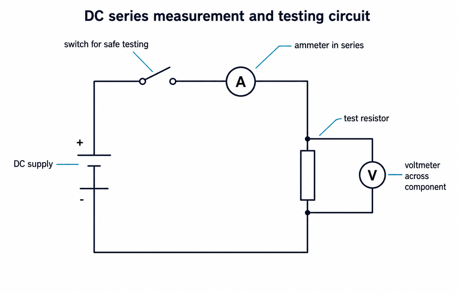
A dc series test circuit is useful because the same current passes through every component in the single loop. To test or measure a component, place the component in the loop with the supply, switch and ammeter. Connect a voltmeter across the component. The ammeter reading gives the current through the component; the voltmeter reading gives the potential difference across it.
In a simple one-component test circuit, the supply potential difference is across the component being tested. If there is more than one component in series, the potential differences across the components add to the supply potential difference. For example, if a 6.0 V supply has 2.5 V across one series component, the remaining series component has across it.
If the ammeter reads 0.30 A and the voltmeter across the component reads 1.5 V, then:
Switch off or disconnect the supply before changing the circuit. This reduces heating in components and avoids short circuits while moving leads.
Most mistakes in this topic come from applying a series rule to a parallel branch, or from starting arithmetic before identifying the circuit layout.
Choose the circuit rule before calculating: parallel branches have the same potential difference, branch currents add, and adding a parallel branch decreases the total resistance qualitatively.