4.2.2a - Series Circuits and Equivalent Resistance
In a series circuit, components are joined in one continuous route, so the same current passes through every component in that route. The supply potential difference is shared between the components, and series resistances add together. These three ideas let you construct, check and calculate dc series circuits without guessing what happens at each component.
Recognising Series Circuits
A series circuit has one route for current to follow through the components. If that route is broken anywhere, the current stops everywhere in the circuit. A parallel circuit has branches, but in this lesson parallel circuits are only a contrast: the calculation work here is for series circuits.
Series circuit
A series circuit is a circuit in which components are connected one after another in a single path for the current.
When you construct or check a series circuit, trace the route from one side of the power supply, through every component, and back to the other side of the power supply. The series part should be one unbroken loop. Measuring instruments have specific positions: an ammeter is placed in series to measure the current in the loop, while a voltmeter is connected across the component whose potential difference is being measured.
[DIAGRAM: asset_name: Series measurement circuit - diagram 1; asset_slug: 020_4_2_2a_series_circuits_and_equivalent_resistance_diagram1; file: diagram_assets/020_4_2_2a_series_circuits_and_equivalent_resistance_diagram1.png; recommended_method: image_gen; description: Exact assessed circuit diagram of a 12 V dc series circuit with a closed switch, ammeter in series, two fixed resistors labelled R1 = 4 ohms and R2 = 8 ohms, voltmeters connected across each resistor, arrows showing the same current of 1.0 A, and labels showing potential differences of 4 V and 8 V adding to 12 V. Circuit symbols, meter positions and labels carry assessed meaning. The surrounding prose states all assessed information for accessibility.]
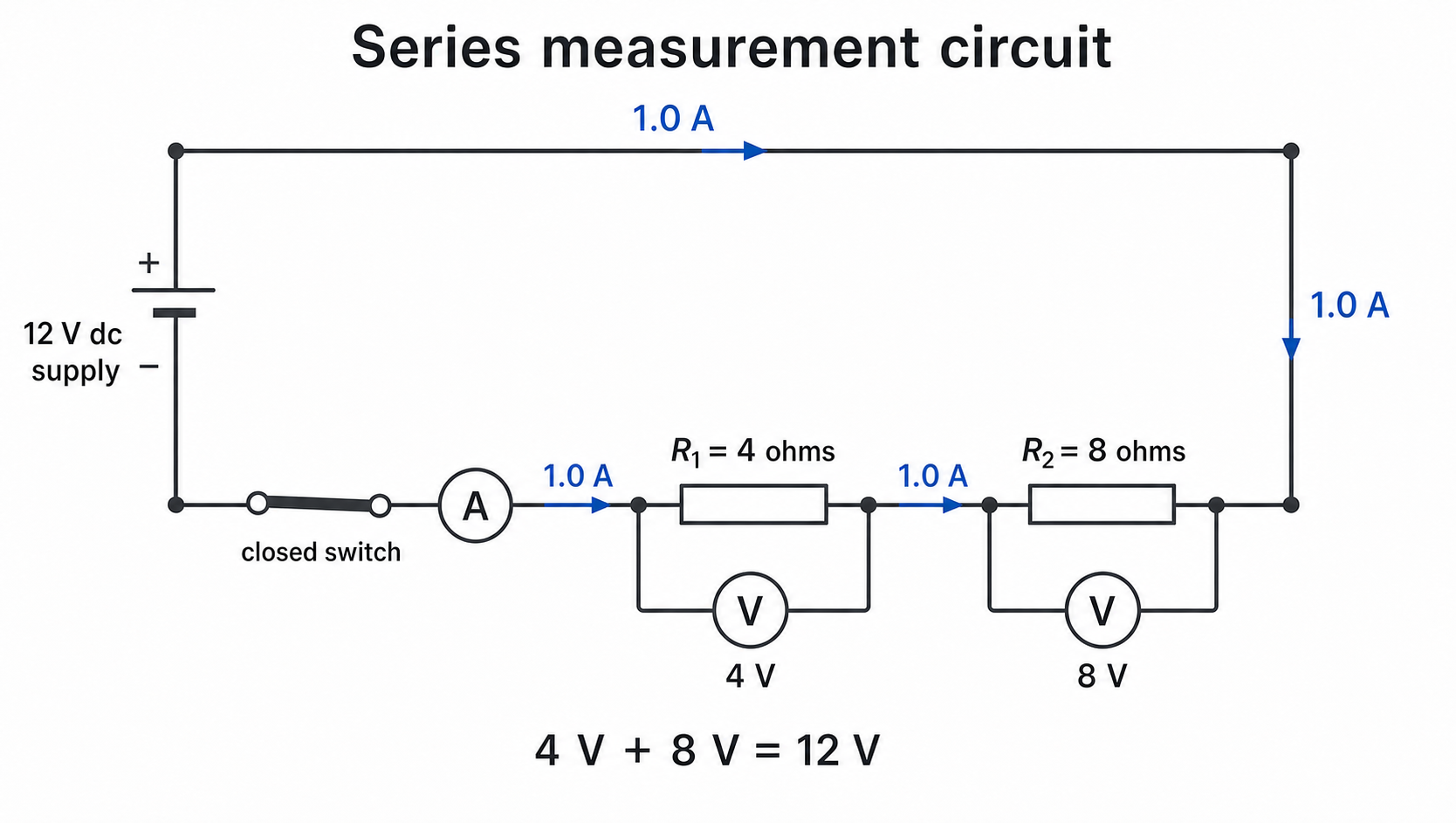
The voltmeter connections do not change the rule that the tested components are in series. The series path is the route through the supply, switch, ammeter and resistors. The voltmeters are measuring connections across chosen parts of that path.
Current and Potential Difference
In a series circuit, there is only one route for charge to flow. Charge cannot choose another branch, so the current is the same through each component in the series loop. An ammeter would give the same reading if it were placed at different points in that loop.
Potential difference behaves differently. The power supply gives energy to each coulomb of charge, and that energy is transferred as the charge passes through components. The total potential difference of the supply is shared between the components.
For two series components:
The shares do not have to be equal. With the same current through both components, the component with the larger resistance has a larger potential difference across it, because .
One common mistake is to say that current is "used up" by the first component. That is not correct. Energy is transferred in components, but charge still flows around the complete loop, so the current is the same before and after each series component.
Equivalent Resistance
Equivalent resistance means the single resistance that would have the same effect on the circuit as the components it replaces. For two components connected in series, the total resistance is the sum of the individual resistances.
Total resistance for two series components
Resistance is measured in ohms, written as . If and , then:
[DIAGRAM: asset_name: Equivalent resistance in series - diagram 2; asset_slug: 020_4_2_2a_series_circuits_and_equivalent_resistance_diagram2; file: diagram_assets/020_4_2_2a_series_circuits_and_equivalent_resistance_diagram2.png; recommended_method: image_gen; description: Exact assessed schematic showing a 12 V dc series circuit with two resistors, 4 ohms and 8 ohms, replaced by an equivalent circuit containing one 12 ohm resistor. Both circuits show the same current of 1.0 A and the formula Rtotal = R1 + R2 = 12 ohms. Generated with built-in Codex Image Gen; nearby prose states the assessed resistor values, circuit structure and calculation labels.]
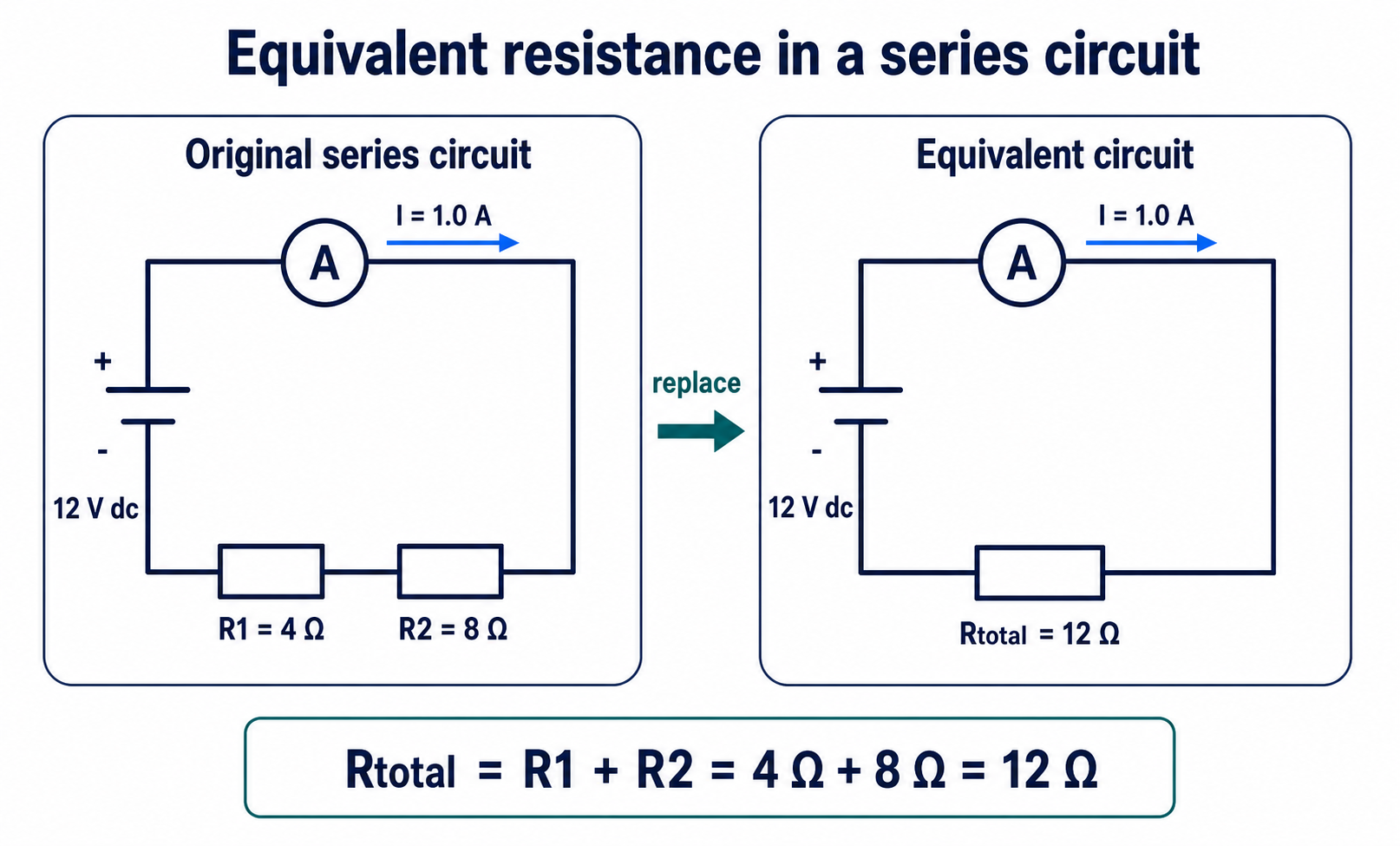
Adding a resistor in series increases the total resistance because charge has to pass through more opposition in the same loop. For the same supply potential difference, a larger total resistance gives a smaller current through the whole circuit.
Series Circuit Calculations
Series-circuit calculations usually work best if you combine the resistors first, then use the total resistance to find the circuit current. The relationship is useful here because it links potential difference, current and resistance.
Worked example: a 12 V dc supply is connected to a resistor and an resistor in series. Calculate the current in the circuit and the potential difference across each resistor.
First find the total resistance:
Then find the current using the supply potential difference and the total resistance:
The current is the same through both resistors, so use for each component:
Check the answer by adding the potential differences:
That equals the supply potential difference, so the calculation is consistent.
Measurement and Testing
A dc series circuit is useful for measurement and testing because the current is steady and the same through each component in the series path. A switch lets you connect the circuit only when taking readings, and a known dc supply gives a fixed supply potential difference.
To measure current in a series circuit, place the ammeter in the single loop. To measure potential difference, connect the voltmeter across the component or part of the circuit being tested. To test the series rules, you can compare ammeter readings at different points in the loop and compare voltmeter readings across the components with the supply potential difference.
For example, in a two-resistor series circuit:
| Check | What you should find |
|---|---|
| Ammeter moved to different points in the loop | same current reading |
| Voltmeter across each resistor | readings add to the supply potential difference |
| Total resistance calculated from | same as the equivalent resistance used with the supply pd to find total current |
If the measured current is not the same at different points in the series loop, the circuit may not be connected as intended, a meter may be in the wrong position, or there may be a loose connection.
These measurement checks are useful because they connect the circuit diagram to evidence: the meter readings should match the series-circuit rules.
For series circuits: current is the same through every component, potential difference is shared between components, and the equivalent resistance of two series components is .