4.2.1.1 - Standard circuit diagram symbols
Circuit diagrams are a compact way to show electrical circuits. They do not try to draw the real apparatus; instead, they use agreed symbols so that anyone can see which components are present and how they are connected. In this lesson you will learn how to recognise, draw and interpret the standard symbols used in AQA GCSE Physics circuit diagrams.
Circuit diagrams and symbols
A circuit diagram is a schematic drawing. This means it shows the important electrical connections, not the real positions, shapes or sizes of the equipment on the bench.
Circuit diagram
A circuit diagram is a drawing that uses standard symbols and joining lines to show the components in an electrical circuit and how they are connected.
The joining lines in a circuit diagram represent wires. They are usually drawn as straight horizontal and vertical lines because straight lines make the connections easier to read. A neat circuit diagram should let another student build the same circuit without needing a photograph of it.
Standard symbols matter because they remove guesswork. A circle with an A inside it means an ammeter. A circle with a cross inside it means a lamp. If students invented their own pictures, the same circuit could be drawn in many confusing ways.
The standard symbols
The symbol reference below shows the symbols you should recognise, draw and interpret. You do not need to explain every component's detailed behaviour in this lesson. For example, the detailed behaviour of thermistors, LDRs, lamps and diodes belongs to a later lesson on resistors.
[DIAGRAM: asset_name: Standard circuit diagram symbols - diagram 1; asset_slug: 013_4_2_1_1_standard_circuit_diagram_symbols_diagram1; file: diagram_assets/013_4_2_1_1_standard_circuit_diagram_symbols_diagram1.png; recommended_method: image_gen; description: Reference sheet of the AQA GCSE standard circuit symbols: open switch, closed switch, cell, battery, diode, resistor, variable resistor, lamp, fuse, voltmeter, ammeter, thermistor, LDR and LED. Nearby prose explains how to use the sheet and keeps detailed component behaviour out of scope.]
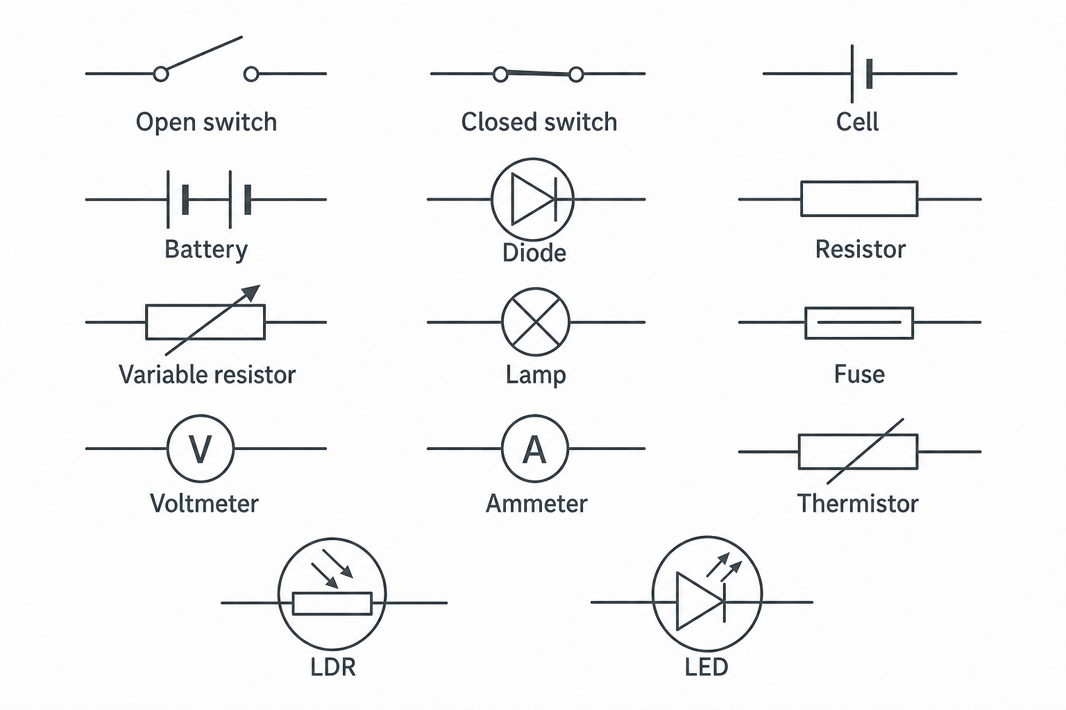
A useful way to group the symbols is by what you need to spot first:
| Group | Symbols to recognise | Drawing cue |
|---|---|---|
| sources and switches | cell, battery, open switch, closed switch | cells have one long plate and one short plate; an open switch has a visible gap |
| components | lamp, fuse, resistor, variable resistor | a lamp is a circle with a cross; a resistor is a rectangle |
| meters | ammeter, voltmeter | a circle with A or V inside |
| diode symbols | diode, LED | a diode has a triangle and a line; an LED also has two arrows showing emitted light |
| sensing components | thermistor, LDR | both are based on a resistor symbol; the LDR has arrows pointing towards it |
A cell is one electrical source. A battery is two or more cells joined together, so the battery symbol repeats the long-short plate pattern. In exam answers, do not call every source a battery if the symbol shows only one cell.
Drawing symbols clearly
When you draw a circuit diagram, clarity matters more than artwork. Use straight joining lines, leave deliberate gaps only where a switch is open, and draw each component with enough space that the symbol cannot be mistaken for another one.
For the common symbols, use these habits:
- draw a cell with one long plate and one short plate
- draw a battery as two or more cells
- draw an open switch with a visible gap and a closed switch with the contact made
- draw an ammeter or voltmeter as a circle with a clear
AorV - draw a variable resistor with an arrow through the resistor
- draw an LED as a diode symbol with two arrows pointing away
- draw an LDR as a resistor in a circle with arrows pointing towards it
Avoid pictorial drawings such as a realistic bulb, a real battery case or a sketch of wires on a bench. Those drawings may look familiar, but they are not standard circuit diagram symbols.
Interpreting diagrams
To interpret a circuit diagram, read it in a steady order:
- Identify each symbol.
- Follow the joining lines to see which components are connected.
- Look for gaps, such as an open switch.
- Look for junctions where wires meet.
- Turn the diagram into a sentence that names the components and their connections.
[DIAGRAM: asset_name: Interpreting a circuit diagram - diagram 2; asset_slug: 013_4_2_1_1_standard_circuit_diagram_symbols_diagram2; file: diagram_assets/013_4_2_1_1_standard_circuit_diagram_symbols_diagram2.png; recommended_method: image_gen; description: Interpreted circuit diagram with numbered callouts. The circuit shows a battery, closed switch, lamp, fixed resistor and ammeter in the main loop, with a voltmeter connected across the lamp.]
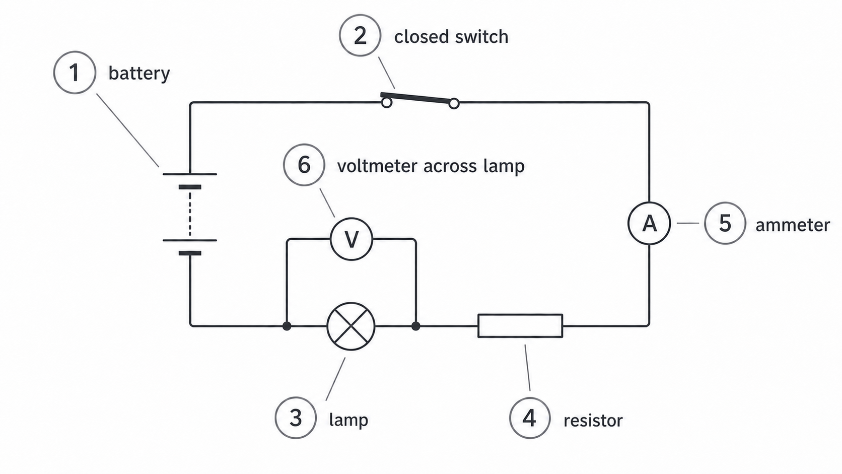
For the example above, a good interpretation is:
The circuit has a battery, a closed switch, a lamp, a resistor and an ammeter in the main loop. A voltmeter is connected across the lamp.
That sentence says what the symbols are and how they are connected. It does not need to say where the components would physically sit on a bench.
That same idea helps you answer interpretation questions: name the symbol, then say what it is connected to.
Exam habits and misconceptions
Most marks on this specification point come from careful recognition and clear interpretation. Slow down enough to avoid these common errors:
- Do not confuse a cell with a battery. A battery has more than one cell.
- Do not confuse an ammeter with a voltmeter. Read the letter inside the circle.
- Do not confuse a diode with an LED. The LED has arrows showing light emitted.
- Do not confuse a variable resistor with an LDR. The variable resistor has an arrow through the resistor; the LDR has arrows pointing towards a resistor inside a circle.
- Do not draw realistic pictures of components when a standard symbol is expected.
- Do not add accidental gaps in wires. A gap changes the meaning of the circuit.
- Do not use this lesson to infer current values, resistance values or series/parallel rules. Those ideas are taught later.
If two wires meet at a junction, make the join clear. If lines only cross over each other in a diagram, do not assume they are joined unless the diagram shows a clear junction.