4.2.1.4b - Thermistors, LDRs And Sensing Circuits
Some resistors have a resistance that changes when their surroundings change. A thermistor responds to temperature, and an LDR responds to light intensity. In this lesson, you will use those changes to explain sensing circuits such as thermostats and lights that switch on when it gets dark.
Sensor Components
A thermistor and an LDR are both resistors, but their resistance is not fixed. They are useful sensors because an environmental change causes an electrical change in a circuit.
Thermistor
A thermistor is a resistor whose resistance changes with temperature. In AQA GCSE Physics, the required thermistor behaviour is: as temperature increases, resistance decreases.
A thermistor can be used in a thermostat. For example, a temperature-control circuit can respond when a room, incubator, fridge, or cooling system reaches a set temperature.
LDR
An LDR, or light-dependent resistor, is a resistor whose resistance changes with light intensity. As light intensity increases, the resistance of an LDR decreases.
That gives the opposite statement for dark conditions: when it gets darker, light intensity decreases, so an LDR's resistance increases. This is why an LDR can be used in a circuit that switches a light on when it gets dark.
[DIAGRAM: asset_name: Thermistor and LDR response graphs - diagram 1; asset_slug: 018_4_2_1_4b_thermistors_ldrs_and_sensing_circuits_diagram1; file: diagram_assets/018_4_2_1_4b_thermistors_ldrs_and_sensing_circuits_diagram1.png; recommended_method: deterministic_drawn; description: Two qualitative assessed graphs on light backgrounds. Left graph: thermistor resistance on the y-axis decreases as temperature on the x-axis increases. Right graph: LDR resistance on the y-axis decreases as light intensity on the x-axis increases. Labels must be readable, with no numerical scale implied.]
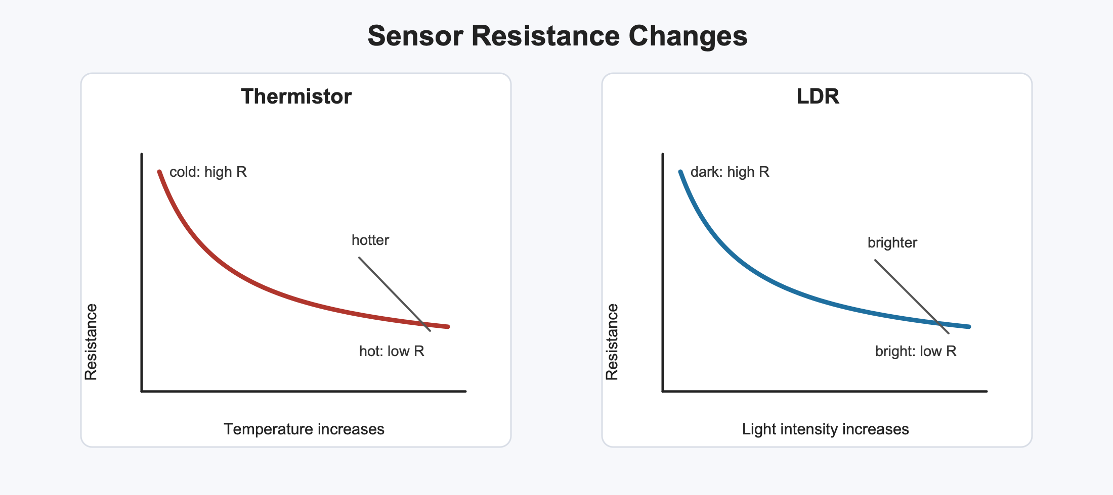
The shapes are normally curves, not straight lines. For this lesson, the important assessment point is the direction of each change, not a particular numerical formula for the curve.
Sensing Circuits
A sensing circuit turns a change in resistance into a useful electrical signal. The signal might be a change in current, or a change in potential difference across part of the circuit. A switching or control unit can then respond when the signal reaches a chosen value.
In a simple series sensing pair, the current is affected by the total resistance. If the sensor's resistance decreases, the total resistance is smaller, so a larger current can flow for the same supply potential difference.
Thermistor example:
- The temperature rises.
- The thermistor's resistance decreases.
- The current or signal p.d. in the sensing circuit changes.
- A control unit can switch a heater off, or switch a cooling fan on, depending on how the circuit has been designed.
LDR example:
- It gets darker.
- Light intensity on the LDR decreases.
- The LDR's resistance increases.
- In a dark-switching circuit, that change can produce the signal used to switch a lamp on.
[DIAGRAM: asset_name: Sensing circuit logic for thermostat and dark switch - diagram 2; asset_slug: 018_4_2_1_4b_thermistors_ldrs_and_sensing_circuits_diagram2; file: diagram_assets/018_4_2_1_4b_thermistors_ldrs_and_sensing_circuits_diagram2.png; recommended_method: image_gen; description: Two circuit panels. Panel A shows a thermistor and fixed resistor as a series sensing pair connected to a low-voltage supply, with an output signal taken to a control unit; annotation says hotter -> thermistor R lower -> signal changes -> heater/fan control. Panel B shows an LDR and fixed resistor series sensing pair with output across the LDR to a control unit; annotation says darker -> LDR R higher -> output signal higher -> lamp on. Circuit symbols and labels must be accurate and readable; the switching unit remains a black box.]
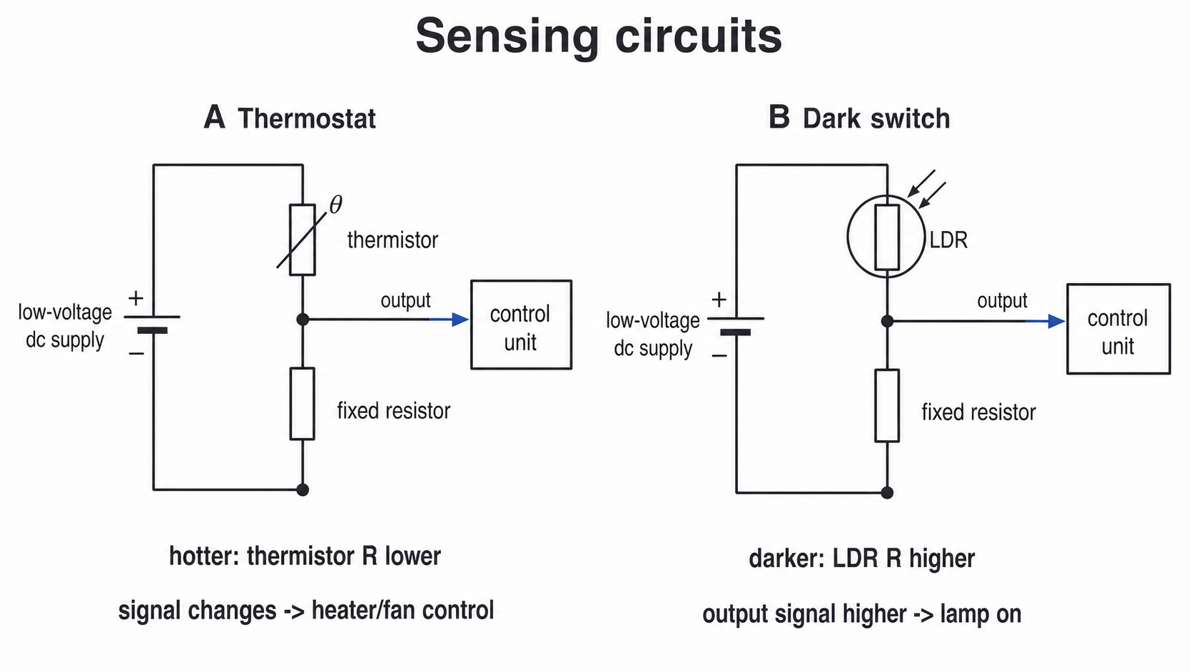
The design detail matters. A thermistor or LDR does not magically "know" what device to turn on. The surrounding circuit decides whether a high or low resistance gives the switching signal.
In the dark-switch panel, the output signal is taken across the LDR. When it gets darker, the LDR's resistance is higher, so the LDR gets a larger share of the supply potential difference. That higher signal p.d. can be used by the control unit to switch the lamp on.
In exam explanations, follow the chain from the physical change to resistance, then to current or p.d., then to the output device.
Now use the same chain in an exam-style explanation: physical change, resistance change, circuit signal, output response.
Measuring Resistance
To measure the resistance of a component in a circuit, measure the current through the component and the potential difference across it.
Resistance From Measurements
In this equation, resistance R is in ohms (Ω), potential difference V is in volts (V), and current I is in amperes (A).
The circuit design has two key meter positions:
- the ammeter is connected in series with the component, so the same current flows through the ammeter and the component
- the voltmeter is connected in parallel across the component, so it measures the potential difference across that component
[DIAGRAM: asset_name: Circuit to measure resistance of a sensor component - diagram 3; asset_slug: 018_4_2_1_4b_thermistors_ldrs_and_sensing_circuits_diagram3; file: diagram_assets/018_4_2_1_4b_thermistors_ldrs_and_sensing_circuits_diagram3.png; recommended_method: image_gen; description: Circuit diagram with low-voltage supply, switch, ammeter in series, a sensor component under test in series, and voltmeter connected in parallel across the sensor. Include small inset examples of the thermistor and LDR symbols. The visual is assessed/exact: meter placement, circuit connections and symbols must be correct.]
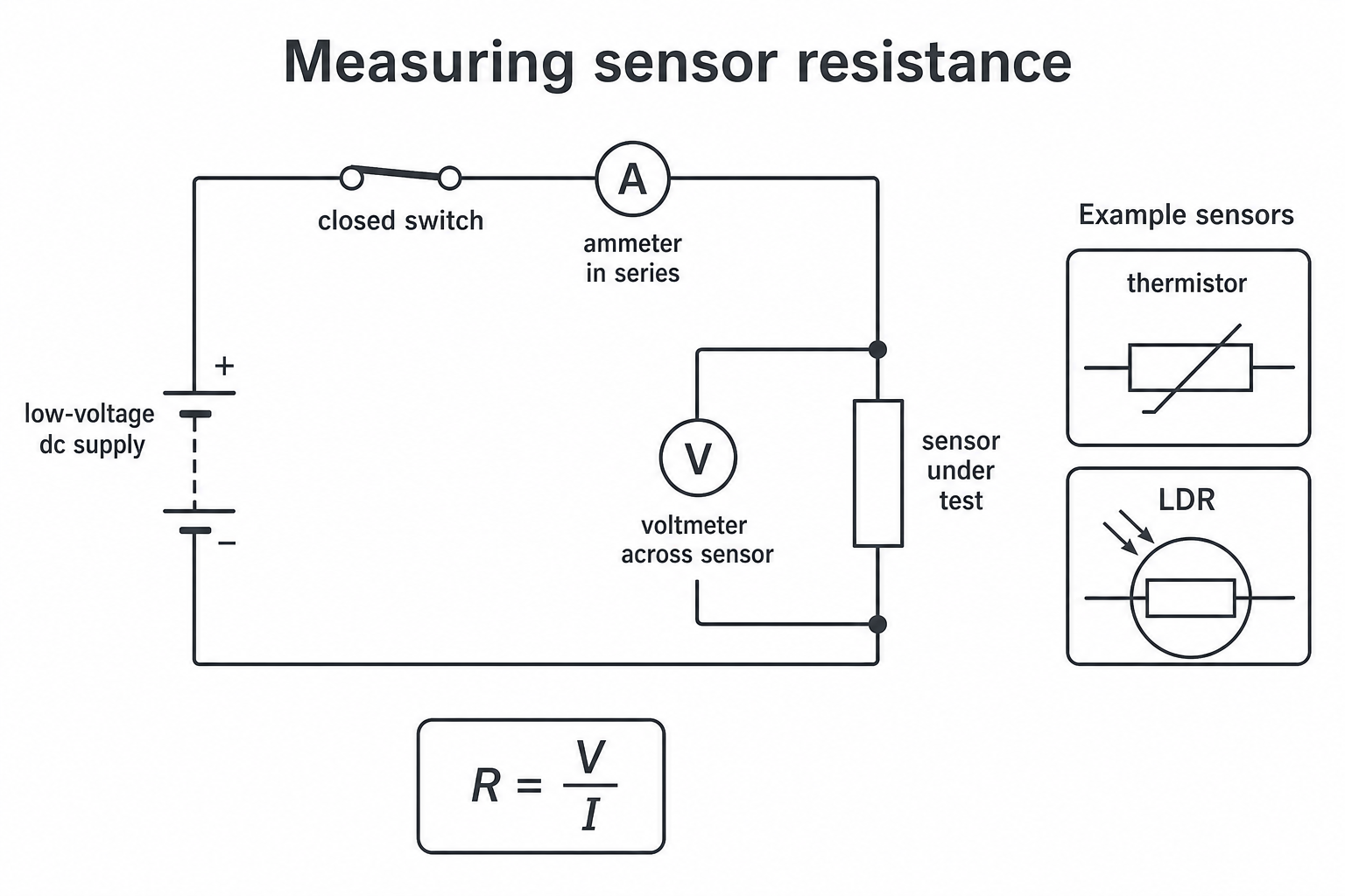
For a thermistor investigation, change the temperature and record the current and p.d. each time. For an LDR investigation, change the light intensity and record the current and p.d. each time. Allow the sensor a short time to respond before taking the readings.
Use a low enough supply p.d. that the component is not damaged and the current is not unnecessarily large. If the component heats up because the current is too high, the resistance measurement may no longer be testing only the intended variable.
Worked example:
A voltmeter across an LDR reads 3.0 V. The ammeter in series reads 0.015 A.
The LDR's resistance is 200 Ω under those light conditions.
Using Graphs
Graphs help you see the relationship between a sensor's resistance and the environmental variable it measures. For this lesson, the useful graphs are:
- resistance against temperature for a thermistor
- resistance against light intensity for an LDR
The axes matter. If resistance is on the vertical axis and temperature is on the horizontal axis, a thermistor graph should slope downwards as you move right. If resistance is on the vertical axis and light intensity is on the horizontal axis, an LDR graph should also slope downwards as you move right.
A graph also helps with calibration. Calibration means linking a meter reading or resistance value to a physical value such as temperature or light intensity. For example, a thermistor can be placed in water with a thermometer, and its resistance recorded as the water cools. The graph can then be used to estimate the temperature from a measured resistance.
You do not need to force a straight line through thermistor or LDR data. If the plotted points form a curve, draw or describe a smooth curve that follows the trend. The important link is between the curve and the component's function as a sensor.
Exam Answer Language
For sensing-circuit explanations, write a clear cause-and-effect chain. Good answers normally have four links:
- State the environmental change.
- State how the sensor's resistance changes.
- State how the circuit current or p.d. signal changes.
- State what the output device or control unit does.
Use exact trend language:
| Component | Input increases | Resistance change | Common application |
|---|---|---|---|
| thermistor | temperature increases | resistance decreases | thermostat / temperature control |
| LDR | light intensity increases | resistance decreases | automatic light control |
Avoid these common errors:
| Error | Better answer |
|---|---|
| "A thermistor's resistance always increases when it gets hot." | For the required GCSE thermistor, resistance decreases as temperature increases. |
| "An LDR has low resistance in the dark." | In the dark, light intensity is low, so an LDR has high resistance. |
| "The lamp turns on because the LDR wants more current." | The circuit uses the LDR's resistance change to change a current or p.d. signal. |
| "Measure resistance by putting a voltmeter in series." | Use an ammeter in series and a voltmeter in parallel across the component. |
Remember that "potential difference" is the exam-board term, but "voltage" is often used informally. In written answers, use potential difference if the question does.
That chain is the safest way to handle both thermostat and dark-switch questions.
Thermistors and LDRs are useful because a physical change causes a resistance change, and a circuit can turn that resistance change into a control signal.