4.5.6.1–4.5.6.3 - Bit patterns and analogue-to-digital conversion
Learn how the same bits can represent different kinds of data, and how converters connect continuously varying physical measurements with discrete digital values.
Bit patterns need an interpretation
A bit pattern acquires meaning from the representation rules used to interpret it.
The byte 01000001 represents unsigned integer 65 under binary place-value rules. Under ASCII it represents 'A'. In a bitmap it might be a colour number, or one colour component of a pixel. In digital audio it might form part of a stored amplitude sample. The bits do not contain a built-in label announcing their type. The program and file format determine how they are grouped and interpreted.
For graphics, a format may group bits into a value for each pixel's colour and arrange the pixels into rows. For sound, a format may group bits into amplitude values ordered by sampling time and audio channel. A header or other metadata, such as image dimensions or audio sample rate, supplies information needed to reconstruct the intended image or sound. Using the wrong dimensions can rearrange an image even when its pixel bytes are unchanged; using the wrong sample rate changes how quickly audio samples are played.
An agreed representation also defines which values are valid and their range. A three-bit unsigned value has eight possible patterns; mapping those patterns to eight sensor levels makes it a measurement representation. This interpretation is different from treating the same three bits as three separate on/off flags.
Continuous and discrete data and signals
Analogue data varies continuously, while digital data uses a set of discrete values.
An analogue measurement can in principle take any value within a range, such as a sensor voltage varying with temperature. Digital data represents a measurement using selected values, such as an integer level from 0 to 7. A recorded value cannot express an arbitrary value between those levels without changing the representation. Digital does not mean “only zero and one as a measurement”: a sequence of bits can encode many discrete values.
A signal is the physical variation carrying information. An analogue signal uses a continuously variable quantity, such as voltage, to represent the data. A digital signal uses defined discrete states, commonly two voltage ranges representing bits. A physical voltage still passes through intermediate values during a transition, but the receiver interprets it as a discrete state. This helps it tolerate small disturbances while the voltage stays within the correct range. Sufficient noise can still cause a bit error, so digital transmission is not immune to corruption.
| Example | Data being represented | Signal or stored representation |
|---|---|---|
| Analogue temperature sensor | Continuously variable measurement | Voltage varies continuously with temperature |
| Digital temperature record | One of a finite set of encoded readings | Bit pattern representing a discrete reading |
| Digital link carrying the record | Discrete bits | Defined signal states interpreted as 0 and 1 |
Keep data values and signals separate in an explanation: one is the information, the other is the physical carrier. A sensor reading can be digitised and later sent as a digital signal.
Sampling, quantisation and the ADC
An analogue-to-digital converter takes a varying analogue input and produces digital codes for measured values.
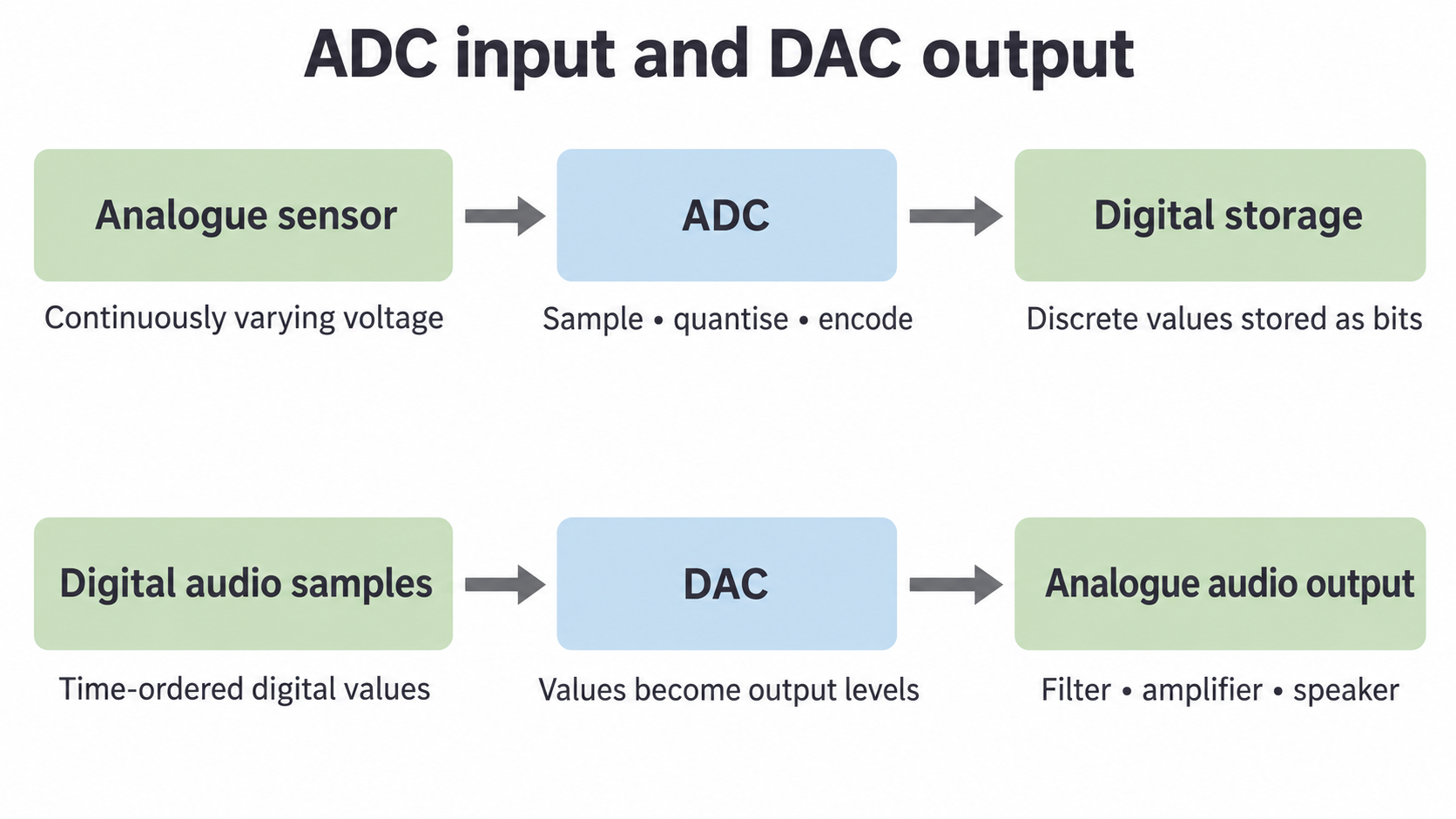
An ADC is used with an analogue sensor because a computer needs digital data to store and process the sensor's voltage. For a time-varying signal, sampling measures its amplitude at selected times, usually evenly spaced. Sampling determines when measurements are taken. Quantisation maps each measured amplitude to one of the available discrete levels. Quantisation determines which value is stored. The level is then encoded as bits. More samples capture more information about changes over time; more levels allow finer amplitude distinctions. These are different improvements.
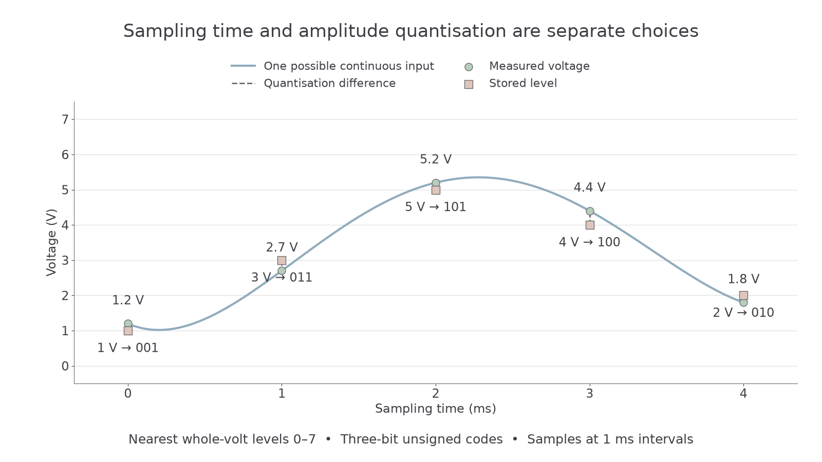
In this deliberately small ADC, the available levels are 0, 1, 2, …, 7 volts, encoded as unsigned three-bit values. It rounds each sample to the nearest level; all measurements in the examples are inside its range and none is exactly halfway.
| Sampling time (ms) | Measured voltage (V) | Quantised level (V) | Digital code |
|---|---|---|---|
| 0 | 1.2 | 1 | 001 |
| 1 | 2.7 | 3 | 011 |
| 2 | 5.2 | 5 | 101 |
| 3 | 4.4 | 4 | 100 |
| 4 | 1.8 | 2 | 010 |
At 1 ms the stored value is 3 V rather than 2.7 V: quantisation introduces a 0.3 V difference. Values between samples are not stored at all. The plotted curve shows one possible continuous signal through those readings, not extra measurements made by the ADC.
[DIAGRAM: asset_slug: adc_samples; description: Exact sample times and nearest one-volt quantisation levels for the worked three-bit ADC example]
For a range split into levels, a -bit code can identify each level. Doubling the level count requires one extra bit. The exact voltage-to-code mapping depends on the stated ADC convention; do not assume every converter uses the rounded endpoints in this example.
The DAC reconstructs an analogue output
A digital-to-analogue converter turns digital values into corresponding analogue output levels.
A DAC reads a binary value and produces a corresponding voltage or current. During audio playback it receives amplitude samples in time order at the intended sample rate. A simple output stage holds each corresponding level until the next value arrives, giving a stepped waveform; a reconstruction filter smooths the changes to produce an analogue audio signal. This is amplified to drive a speaker, whose movement produces a sound wave. Converting digital audio to an analogue signal is the most common use of a DAC.
For the worked ADC's codes 001, 011, 101, 100, 010, a matching DAC outputs levels 1, 3, 5, 4 and 2 V at the intended times. The original exact readings 1.2, 2.7, 5.2, 4.4 and 1.8 V are no longer stored, so the DAC cannot simply retrieve them. Reconstruction uses the available samples and the system's assumptions; it cannot guarantee recovery of information lost through coarse quantisation or inadequate sampling.
In a temperature logger the input path is sensor → ADC → digital processing/storage. In an audio player the output path is digital samples → DAC → analogue amplifier → speaker. They have opposite conversion directions. A DAC does not measure an analogue input, and an ADC does not generate the analogue playback waveform.
[DIAGRAM: asset_slug: adc_dac_paths; description: ADC input from an analogue sensor to digital storage, contrasted with DAC output from digital audio samples to the analogue audio circuit]