4.4.5.1 - Turing machines as a model of computation (C#)
Represent and trace a simple Turing machine, relate its rules to a C# simulator and explain what the model contributes to computation. This route uses written C# tasks and is incomplete: runnable support pending.
Tape, states and transition rules
A Turing machine performs a computation using a fixed finite program and a tape on which it can read and write symbols.
Its structure consists of a finite set of states, a finite alphabet of tape symbols, a tape divided into squares and a sensing read-write head. The head reads one square, may replace its symbol, and moves one square left or right as specified by a transition. One state is the start state; states with no outgoing transitions are halting states. AQA examination machines have one tape that is infinite in one direction. Use positions 0, 1, 2, … here, with further blank squares to the right; no rule in an example may move left beyond position 0.
The machine's finite description and its unbounded tape have different roles. Its current state is finite control information. The tape holds the input and any working information; it is not restricted to a fixed finite number of cells in the formal model. The blank symbol is a member of the tape alphabet and marks initially unused cells. It is not the empty string.
Write a transition as
meaning: in state , reading , write , move in direction , and enter . Here is L or R.
The tuple order is explicitly defined because a supplied question may use another convention. For example, writes 1 over the current 0, moves one square left and changes to . The newly read symbol at that destination is used only by the next transition. This example is legal only when the head is to the right of the left boundary.
In a state transition diagram, the same rule is an arrow from to labelled . The source and destination states correspond to the first and next-state entries of the function; the arrow label supplies the read symbol, write symbol and movement. An unlabelled incoming arrow marks the start state. A halting state has no outgoing arrows; halting is not defined merely by drawing a double circle, which commonly means acceptance in an FSM.
Representing and tracing a machine
A trace records the tape, head position and state after each transition so that the computation can be checked exactly.
Represent a nonnegative integer in unary as that many consecutive 1 symbols followed by blanks. Start the head at position 0 in . This machine increments the represented integer by scanning over its 1's and replacing the first blank with another 1. Its tape alphabet is , its states are , and halts.
[DIAGRAM: asset_slug: unary_increment_turing; description: Unary increment Turing machine with q0 scanning right over 1 symbols, then writing 1 on the first blank and moving right to halting state qH.]
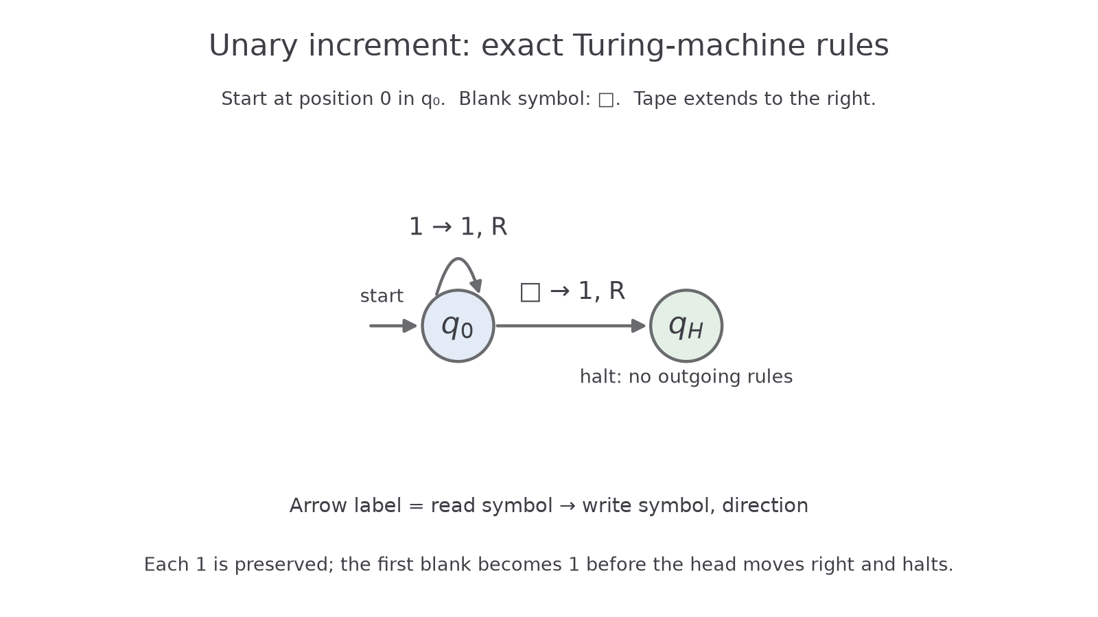
The loop arrow preserves each existing 1 and moves right. The arrow to writes the extra 1 and moves to the next blank. The function and diagram describe exactly the same two rules; no transition leaves .
For input representing 3, the visible prefix initially is ; all omitted cells are also blank.
| Transitions completed | State | Head position | Tape prefix at positions 0–4 |
|---|---|---|---|
| 0 | 0 | ||
| 1 | 1 | ||
| 2 | 2 | ||
| 3 | 3 | ||
| 4 | 4 |
The result represents 4. Reading a blank does not itself halt the machine: the applicable transition writes, moves and enters the halting state. For input zero, the first cell is blank and this same rule completes the computation in one transition. For a finite unary input of length , the machine makes transitions and never moves left, so it respects the one-direction-infinite tape boundary.
To draw a machine from a transition function in a notebook, create one node for each state, mark the start, and add one labelled arrow per rule. To write the function from a diagram, take each arrow's source, read symbol, destination, write symbol and direction in the declared tuple order. Check that an intended halting node has no outgoing rules. Assessment here uses supplied diagrams, written rules and traces; notebook drawing is useful construction practice.
Simulating a transition in C#
A C# simulator represents the tape and control state as data, while its update order follows the formal transition rules.
Continue this lesson.
You’re previewing NovaLearn without an account. Create a free account to read the rest.
Create free account