3.2.3(e)-(f) - Equilibrium and triangle of forces
Equilibrium is the physics word for a situation where forces do not make an object accelerate and torques do not make it start rotating. In this lesson you will learn the two checks for equilibrium, then use a triangle of forces for three coplanar forces. The aim is to make force diagrams useful: not just drawing arrows, but turning them into clear equations and conclusions.
Two Equilibrium Checks
An object is in equilibrium when its motion is not changing. A stationary object in equilibrium stays stationary. An object already moving at constant velocity can also be in equilibrium, because zero resultant force means zero acceleration.
For a real extended object, there is a second check. The forces must also produce no resultant torque, so the object does not gain angular acceleration.
Equilibrium
An object is in equilibrium when the resultant force on it is zero and the resultant torque on it is zero. Its translational and rotational motion do not change.
Equilibrium Conditions
Here, F_x and F_y are perpendicular components of the forces, usually horizontal and vertical. The symbol tau represents torque or moment. For this lesson, read sum tau = 0 as "the total clockwise moment equals the total anticlockwise moment" about the chosen point.
The key word is resultant. An object in equilibrium can still have several forces acting on it. The forces have not disappeared; their vector sum is zero.
For example, a book resting on a horizontal table has weight downwards and a normal contact force upwards. If those forces have equal magnitude and act along the same vertical line, the resultant force is zero and there is no turning effect. The book is in equilibrium.
[DIAGRAM: asset_name: Lesson 3.02.3b: Equilibrium And Triangle Of Forces - diagram 01; asset_slug: 3_02_3b_equilibrium_and_triangle_of_forces__diagram_01; recommended_method: drawn_physics; description: Clean 16:9 drawn physics diagram comparing two horizontal rods. Left panel: two equal opposite vertical forces at opposite ends of a rod, labelled 60 N up and 60 N down, with note zero resultant force but non-zero torque and a curved rotation arrow. Right panel: a rod with central 120 N weight and two symmetric 60 N upward support forces, labelled zero resultant force and zero resultant torque. White background, only #6A6B6E, thin arrows and labels.]
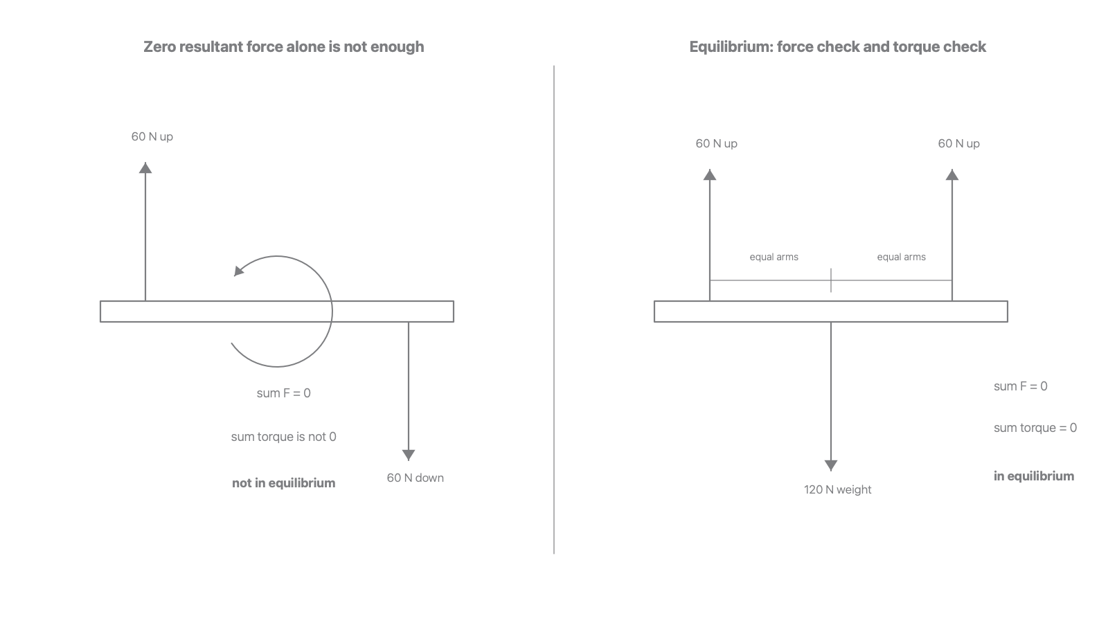
The diagram shows why a force check alone is not enough. In the left-hand case the upward and downward forces are equal and opposite, so the resultant force is zero. However, because their lines of action are separated, they produce a turning effect in the same rotational sense. The rod is not in equilibrium.
In the right-hand case the upward support forces add to the downward weight, so the resultant force is zero. The arrangement is symmetric, so the clockwise and anticlockwise moments also cancel. That rod is in equilibrium.
Worked example: checking both conditions
A light horizontal rod has a 60 N upward force at its left end and a 60 N downward force at its right end. The ends are 2.0 m apart.
- Resultant force:
60 Nup and60 Ndown give zero resultant force. - Torque about the centre: each force acts
1.0 mfrom the centre and each tends to rotate the rod in the same direction. - Total torque magnitude:
60 x 1.0 + 60 x 1.0 = 120 N m.
The rod is not in equilibrium because the resultant torque is not zero.
Force Diagrams For Equilibrium
A force diagram is the bridge between the physical situation and the calculation. Before adding numbers, decide what object is being considered and draw only the forces acting on that object.
For equilibrium questions, a good force-diagram routine is:
- Isolate one object or one point.
- Draw each external force with a direction and a label.
- Choose perpendicular axes.
- Resolve angled forces into components if needed.
- Write
sum of components = 0along each axis. - For an extended object, also check moments or torques.
Do not include the force that the object exerts on something else. If a hanging sign pulls down on a string, the force on the sign from the string is the tension pulling up along the string. The action-reaction pair acts on different objects, so it does not belong on the same force diagram.
Coplanar Forces
Coplanar forces act in the same plane. A flat page can represent their directions without needing a third dimension.
The data booklet gives component relationships for a force F at an angle theta to the horizontal axis:
Vector Components
These equations only match the diagram if theta is measured from the horizontal. If the angle is measured from the vertical, the sine and cosine swap roles. This is one of the most common errors in equilibrium calculations.
Worked example: a symmetric hanging sign
A sign of weight 120 N is supported by two identical cables. Each cable makes an angle of 35 degrees above the horizontal. Find the tension T in each cable.
The sign is stationary, so it is in equilibrium.
Horizontal components:
These cancel because the cables are identical and symmetric.
Vertical components:
So:
A sensible final answer is:
The tension is larger than half the weight because each cable has only a vertical component of its tension supporting the sign. The horizontal components cancel each other and do not support the weight.
Triangle Of Forces
For three coplanar forces in equilibrium, the forces can be represented by a closed triangle when drawn head-to-tail. This is called the triangle of forces.
Triangle Of Forces
For three coplanar forces in equilibrium, the three force vectors can be drawn head-to-tail to form a closed triangle. The closed triangle shows that the vector sum of the forces is zero.
The physical diagram and the triangle of forces are different drawings.
- The physical diagram shows where the forces act on the object.
- The force triangle shows the vectors placed head-to-tail.
- The sides of the triangle represent the magnitudes and directions of the forces.
- The triangle must close. If there is a gap, the gap represents a non-zero resultant force.
[DIAGRAM: asset_name: Lesson 3.02.3b: Equilibrium And Triangle Of Forces - diagram 02; asset_slug: 3_02_3b_equilibrium_and_triangle_of_forces__diagram_02; recommended_method: drawn_physics; description: Clean 16:9 drawn physics diagram with two panels. Left panel shows a small ring supporting a hanging load: two angled cable tensions T1 and T2 upward-left/upward-right and weight W downward. Right panel shows the same three vectors drawn head-to-tail as a closed triangle, labelled T1, T2 and W, with arrowheads in order and note closed triangle means resultant force zero. White background, only #6A6B6E, thin lines and labels.]
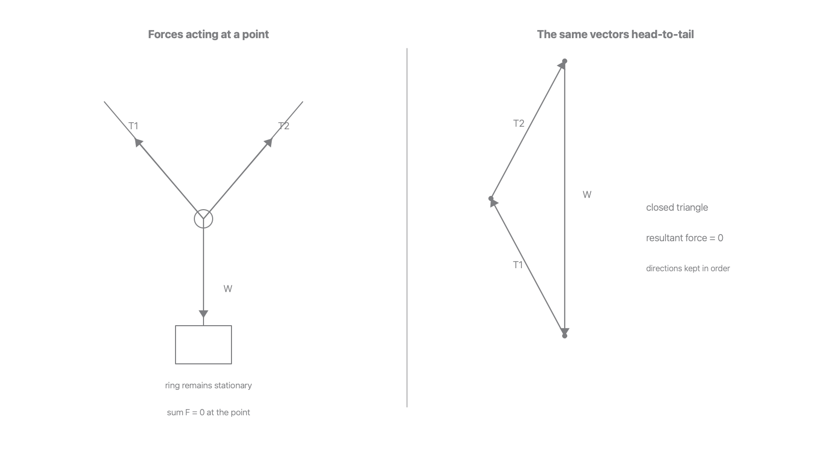
The triangle can be used qualitatively or quantitatively. Qualitatively, it proves that if the three vectors close, the resultant force is zero. Quantitatively, it lets you use triangle geometry such as Pythagoras' theorem, the angle sum of a triangle, the sine rule or the cosine rule.
Worked example: finding the balancing force
Two forces act at a point:
30 Neast40 Nnorth
Find the third force needed for equilibrium.
First find the resultant of the two known forces. They are perpendicular, so:
The resultant of the first two forces acts north-east. The third force must be equal and opposite to that resultant, so it has magnitude 50 N and acts south-west.
The direction angle can be found from:
so theta = 53 degrees north of east for the resultant. The balancing force is therefore 53 degrees south of west, or equivalently directed opposite the resultant.
Components Or Triangle
The component method and the triangle method are two ways of saying the same vector fact.
Using components:
Using a triangle:
the three vectors close when drawn head-to-tail.
The best method depends on the information given.
| Information given | Useful method | Why |
|---|---|---|
| Horizontal and vertical directions are obvious | Components | The equilibrium equations are direct. |
| Forces make a right-angled triangle | Pythagoras and trigonometry | Quick for perpendicular components. |
| Three force directions form a non-right triangle | Sine rule or cosine rule | The force triangle contains the useful angles. |
| A scale drawing is requested | Triangle of forces by scale | The side lengths represent force magnitudes. |
For a scale drawing, choose a scale such as 1 cm represents 10 N, draw each force vector in the correct direction and order, and measure the missing side or angle. For a calculation, use the same geometry but keep the numbers exact until the final rounding step.
Worked example: unequal cable angles
A small object of weight 180 N is held by two cables. The left cable makes 40 degrees above the horizontal and has tension T_L. The right cable makes 55 degrees above the horizontal and has tension T_R. Find both tensions.
Horizontal equilibrium:
So:
Vertical equilibrium:
Substitute the expression for T_R:
This gives:
Then:
Check the answer physically. The right cable is steeper, so it needs a larger tension than the left cable to balance the horizontal component while also helping support the weight. Both tensions are plausible.
OCR-Style Routine
Equilibrium questions usually reward a clear method more than a long explanation. Use this routine:
- State the object or point being considered.
- State the equilibrium condition being used.
- Choose axes or a moment point.
- Write equations from the diagram.
- Substitute values with units.
- Give the final answer with sensible significant figures.
- Check the physical direction and size of the answer.
For an extended object, do not stop after sum F = 0. If the question is about a beam, ladder, rod, bridge or object with forces at different positions, ask whether the torques cancel. For three forces acting at the same point, the torque issue is usually removed because all the lines of action meet at the point; then the triangle of forces or component equations decide the equilibrium.
There is no explicit PAG attached to this lesson, but a practical context is still possible. A student might use a force board, newton meters and a protractor to test three-force equilibrium. A strong method would:
- use strings meeting at a small ring so the forces are close to concurrent;
- measure the three force magnitudes using newton meters or known weights;
- measure angles with a protractor from a fixed reference line;
- draw a scale vector triangle or resolve the forces into components;
- repeat readings and keep the ring stationary before recording data;
- comment on uncertainty in angle readings, newton-meter resolution and friction at pulleys if used.
This practical language stays inside the lesson boundary because it supports the condition for equilibrium of three coplanar forces. It does not require a separate required-practical label.
OCR-Style Routine Summary
For equilibrium, ask two questions: is the resultant force zero, and is the resultant torque zero? For three coplanar forces acting at a point, a closed head-to-tail triangle is the visual test for zero resultant force.