1.2.2(a)-(e) - Measurement apparatus and accuracy
In this lesson you learn how the specification expects you to choose and use basic measuring apparatus. The focus is not just naming the instrument: it is reading it properly, reducing avoidable error, and explaining why one method gives a better measurement than another. These skills appear throughout practical physics, from measuring a wire diameter to timing an oscillating mass.
Choosing apparatus for the quantity
Start every practical measurement by asking two questions:
- What quantity is being measured?
- What scale and resolution are needed for that quantity?
This 1.2.2(a) and (b) boundary expects you to use both analogue apparatus and digital instruments. Analogue apparatus has a physical scale, pointer or meniscus. Digital apparatus gives a numerical display.
Analogue apparatus
An analogue measuring instrument is read from a continuous scale, pointer, mark or meniscus. Examples include a metre rule, thermometer, pressure gauge, newton meter, protractor and measuring cylinder.
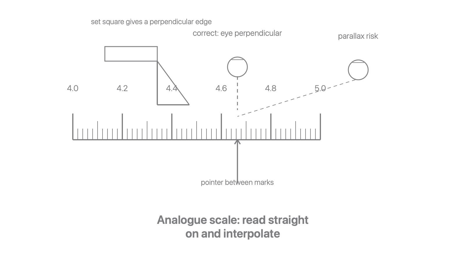
Analogue readings often require judgement between scale markings. If the pointer lies halfway between 4.2 and 4.3 N on a force meter, you should not simply write "between the marks"; you estimate a sensible interpolated value such as 4.25 N if the scale allows that reading.
[DIAGRAM: asset_name: analogue_scale_interpolation; Lesson 1.02.2a: Measurement Apparatus And Accuracy - diagram 01; asset_slug: measurement_apparatus_and_accuracy__diagram_01; recommended_method: drawn_physics; description: A clean 16:9 apparatus diagram showing an analogue scale from 4.0 to 5.0 with minor divisions, a pointer between two marks, an eye directly perpendicular to the scale labelled correct reading, a second angled eye labelled parallax risk, and a set square placed against an object to show perpendicular alignment. Use only #6A6B6E on white.]
Digital instruments are usually easier to read because there is no interpolation between marks. A mass balance, digital stopwatch, light-gate timer and digital multimeter all display numbers. The display resolution, however, is not the whole story.
Resolution
Resolution is the smallest change in a quantity that an instrument can detect or display. A stopwatch displaying to 0.01 s has a display resolution of 0.01 s.
A digital multimeter is included in this row because it can measure current, voltage and resistance. You still need to select the correct function and range, connect the meter appropriately in the actual practical, and record the unit. This lesson does not cover constructing circuits; it only treats the multimeter as a digital measuring instrument.
Worked example: choosing apparatus
A student needs to measure these quantities:
- the diameter of a thin wire;
- the mass of a trolley;
- the angle between two strings;
- the time for a trolley to pass a point.
Suitable choices are:
- wire diameter: micrometer or vernier/digital calipers, because the distance is small;
- mass: digital balance, because mass is a digital measurement in the specification list;
- angle: protractor, read as an analogue scale;
- time: stopwatch or light gate, depending on whether manual reaction time is acceptable.
Notice that the best answer usually includes the reason. "Micrometer" is weaker than "micrometer because the diameter is small and needs a smaller resolution than a metre rule".
Reading analogue scales accurately
Analogue apparatus can give good measurements only if the reading technique is controlled. The most common student mistakes are reading from an angle, forgetting units, and recording more digits than the scale justifies.
Parallax error
Parallax error is an apparent shift in a reading caused by viewing a scale from the wrong angle. It is reduced by placing the eye perpendicular to the scale or pointer.
For a metre rule, protractor, thermometer, pressure gauge, force meter or measuring cylinder, use this routine:
- Check the zero and the unit.
- Place the eye level with the scale or perpendicular to the pointer.
- Interpolate only when the scale markings make this reasonable.
- Record the value with its unit.
- Repeat if the reading can vary because of alignment, judgement or the object shape.
For volume in a measuring cylinder, the meniscus should be read at eye level. For a force meter, make sure the scale is vertical if the force acts vertically and that the pointer is not stuck. For angles, place the protractor centre and baseline carefully before reading.
Accuracy is about closeness to the true value. Precision is about the agreement, or spread, of repeated measurements. Resolution is the smallest change an instrument can detect and is a separate instrument property.
Accuracy
Accuracy describes how close a measured value is to the true value.
Precision is a different idea, even though the two words are often confused in practical answers.
Precision
Precision is the closeness of agreement between independent measurements obtained under the same conditions; a smaller spread means greater precision.
Do not write that a digital instrument is automatically more accurate than an analogue one. A digital display can still have a zero error, poor calibration, wrong range or poor alignment in the method.
Worked example: interpolating a scale
A force meter has labelled marks at 4.0 N and 5.0 N, with ten equal small divisions between them. The pointer is halfway between the 4.6 N and 4.7 N marks.
Each small division is:
The reading is halfway between 4.6 N and 4.7 N, so a sensible interpolated value is:
The value should not be recorded as 4.6538 N because the scale cannot resolve that many digits.
Methods that improve accuracy
The specification names several practical methods that improve measurement accuracy. These methods reduce a specific source of error; they are not magic phrases to add to every answer.
Timing over multiple oscillations is used when one period is short compared with human reaction time. If a pendulum takes about 1 s for one oscillation, a start/stop reaction delay of a few tenths of a second is large. Timing 20 oscillations makes the same start/stop delay a much smaller percentage of the total measured time.
Mean time per oscillation
Here is the mean period of one oscillation, is the measured time for complete oscillations, and is the number of oscillations timed.
Worked example: timing multiple oscillations
A pendulum completes 20 oscillations in 31.8 s.
If the student had timed only one oscillation, the stopwatch reaction-time uncertainty would be a much larger fraction of the time. Timing many oscillations and dividing by the number of oscillations reduces the percentage uncertainty in the period.
A fiducial marker is a fixed reference mark used to judge exactly when an object passes a position. For an oscillating pendulum, a vertical mark behind the equilibrium position makes the timing point consistent from one oscillation to the next.
Alternatively, a light gate at the equilibrium position or a motion sensor connected to a data logger can determine the period electronically, provided the system is set to measure a complete oscillation.
Fiducial marker
A fiducial marker is a fixed reference mark used to make position or timing judgements repeatable.
Set squares and plumb lines solve alignment problems. A set square can help measure a length perpendicular to a surface or align an object with a ruler. A plumb line gives a vertical reference, useful for judging whether a ruler, pendulum or falling path is vertical.
Take care with the word "repeat". Repeated measurements reveal the spread and possible anomalies, allowing precision and repeatability to be assessed. Repeatability refers to precision over a short timescale when the same person or group uses the same equipment in the same place. Reproducibility instead refers to precision over a wider timescale when different people use equivalent equipment in different, but equivalent, places. If the variation is random, calculating a mean reduces its influence on the final estimate. Neither step removes a systematic error such as a zero error or a misaligned ruler, so a better method also identifies and reduces specific sources of error.
Stopwatches and light gates
A stopwatch is simple and useful when an event lasts long enough that reaction time is a small part of the total time. The display may read to 0.01 s, but the person pressing the button usually causes a larger uncertainty than the display resolution.
A light gate is a timing sensor. It has a transmitter and receiver; when an object or interrupt card breaks the beam, the timer starts, stops or records how long the beam is blocked.
[DIAGRAM: asset_name: timing_methods; Lesson 1.02.2a: Measurement Apparatus And Accuracy - diagram 02; asset_slug: measurement_apparatus_and_accuracy__diagram_02; recommended_method: drawn_physics; description: A 16:9 two-panel drawn physics diagram. Left panel: pendulum bob passing a fiducial marker with a stopwatch labelled time N oscillations. Right panel: trolley with interrupt card passing through two light gates connected to a timer, with beam lines and labels for gate 1, gate 2 and measured time interval. Use only #6A6B6E on white.]
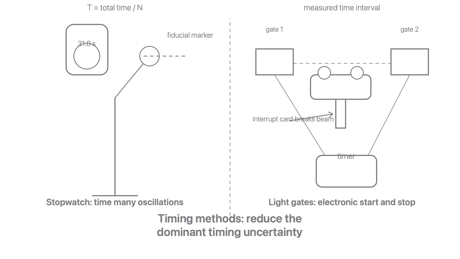
Light gates reduce the human reaction-time part of the uncertainty because the timer is triggered electronically. They are often better for fast motion, repeated trials and short time intervals. They still require careful alignment: the interrupt card must pass cleanly through the beam, the distance between gates or the card length must be measured accurately, and the timer must be set to the correct mode.
Worked example: using a light gate to time a moving trolley
A trolley has a rectangular interrupt card of length 5.00 cm attached to it. A light gate records the time for which the beam is blocked as 0.142 s.
The light gate has directly measured the time taken for the card length to pass the beam. If this is used to find speed, first convert the length:
Then:
The speed calculation is not the main point of this lesson. The main point is that the light gate gives a repeatable timing trigger without a person deciding exactly when to press a stopwatch.
Calipers and micrometers
Calipers and micrometers are used for small distances where a metre rule would give too large a percentage uncertainty. This boundary includes digital or vernier scales, so you should be comfortable with both the instrument choice and the reading technique.
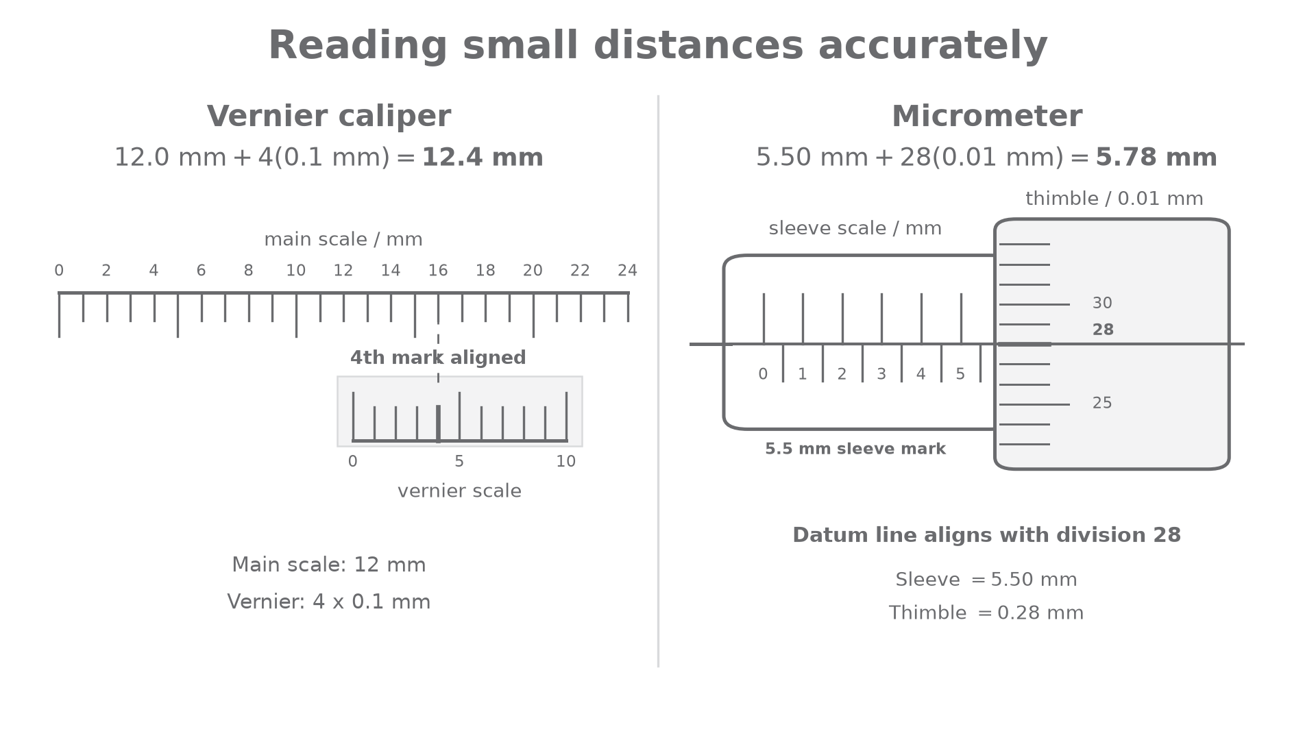
Vernier calipers can measure external diameters, internal diameters and depths. A vernier scale lets you read a fraction of the main-scale division by finding which vernier mark lines up with a main-scale mark. Digital calipers remove the scale-reading step but not the need to zero the instrument and hold it square to the object.
A micrometer screw gauge is usually better for very small thicknesses or wire diameters. It uses a screw thread, a sleeve scale and a rotating thimble scale. The ratchet should be used so the object is gripped consistently and not crushed.
[DIAGRAM: asset_name: small_distance_reading; Lesson 1.02.2a: Measurement Apparatus And Accuracy - diagram 03; asset_slug: measurement_apparatus_and_accuracy__diagram_03; recommended_method: drawn_physics; description: A 16:9 drawn physics diagram with two labelled panels. Left: simplified vernier caliper scale showing main scale, vernier scale, aligned vernier mark and reading 12.4 mm. Right: simplified micrometer sleeve and thimble showing sleeve reading 5.5 mm plus thimble reading 0.28 mm equals 5.78 mm, with ratchet and anvil/spindle labels. Use only #6A6B6E on white.]
Good small-distance technique includes:
- close the jaws first and check for zero error;
- hold the jaws square to the object;
- use the micrometer ratchet rather than over-tightening the thimble;
- repeat at different positions and orientations if the object may not be uniform;
- record the unit and use a sensible number of decimal places for the instrument.
Worked example: repeated diameter readings
A wire diameter is measured with a digital micrometer at four different positions:
0.456 mm, 0.459 mm, 0.455 mm, 0.458 mm
The mean diameter is:
The range of the readings is:
The range describes the spread, so it is useful when judging precision and repeatability. For OCR H556, uncertainty estimates are based on the characteristics of the apparatus rather than the spread of repeated measurements. Use a stated instrument uncertainty where one is given. If none is given, OCR assumes an uncertainty of plus or minus the resolution in each digital reading. For example, if this micrometer has a resolution of 0.001 mm, the assumed apparatus uncertainty in each reading is . State the assumption used.
Explain It Back
Use this as a self-explanation check after the section above. It is for diagnosing what you can already explain, not for learning new material from scratch.
Before moving on, test whether you can separate display resolution from the quality of the whole method.
Writing practical answers
In practical questions, a strong answer usually names the apparatus and explains the method feature that improves the measurement. Keep the wording specific.
Weak answer:
"Use better equipment and repeat it."
Stronger answer:
"Measure the wire diameter with a micrometer at several positions along the wire and in two perpendicular orientations. Calculate the mean diameter, use the range to describe the spread, and state the micrometer's resolution or marked uncertainty."
That answer is better because it states the apparatus, the repeated positions, the orientation check and the processing, while keeping the spread of repeats separate from the apparatus uncertainty.
When choosing between a stopwatch and light gates, make the comparison about the dominant uncertainty. For long events, a stopwatch may be acceptable. For short events or fast-moving objects, reaction time can dominate, so a light gate is usually more appropriate.
When choosing between a ruler, calipers and a micrometer, make the comparison about the size of the distance and percentage uncertainty. A metre rule might be fine for a 0.80 m length but poor for a 0.50 mm wire diameter.
Practical marks often reward the reason behind the apparatus choice: resolution, alignment, repeatability, zero error, reaction time, and whether the method reduces the dominant uncertainty.
Final check for this lesson boundary:
- analogue apparatus: length/distance, temperature, pressure, force, angle and volume;
- digital instruments: time, current, voltage, resistance and mass;
- accuracy methods: multiple oscillations, fiducial marker, set square and plumb line;
- timing: stopwatch and light gates;
- small distances: calipers and micrometers with digital or vernier scales.
Rows about circuit construction, oscilloscopes, wave apparatus, lasers, ICT/data logging as a separate technique, and ionising radiation belong to the sibling 1.02.2 lessons, not this one.