1.4.3 - Boolean problems, gates and truth tables
Boolean logic turns a precise two-state decision into an expression, a circuit and a table of every possible outcome. You will learn to move between these representations while checking that they describe the same rule.
Defining a Boolean problem
A Boolean variable represents one of two logical states, true or false; in circuit tables we normally write these as 1 and 0.
Start by defining what each variable means. For a workshop ventilation system, let mean the room is too hot, mean fumes are detected and mean maintenance mode is selected. These are complete propositions. A temperature such as 27 degrees is a measurement; the proposition “temperature exceeds the threshold” is a Boolean condition derived from it.
Suppose the fan should run when the room is too hot or fumes are detected, but only when maintenance mode is off. The requirement becomes
The brackets make the intended grouping explicit. “But only when maintenance mode is off” applies to the entire demand , rather than just to fumes. Thus gives : maintenance prevents operation even though the room is hot.
The wording and variable definitions matter as much as the symbols. If instead meant “maintenance is complete”, the negation would no longer express the same policy. Likewise, a condition that the fan must never run while the cover is open needs an explicit variable and restriction; a truth table cannot infer an unstated safety requirement.
AND, OR, NOT and XOR
Each logic operator gives a definite output for its input states, so its name alone is insufficient without its truth condition.
| Operator | Output is 1 when… | OCR printed notation | Recognised alternative notation |
|---|---|---|---|
| AND | Both inputs are 1 | , A AND B | |
| OR | At least one input is 1 | , A OR B | |
| NOT | Its single input is 0 | , NOT A, ~A | |
| XOR | Exactly one of two inputs is 1 | , A XOR B |
Exclusive OR (XOR)
Exclusive OR gives 1 when exactly one of its two inputs is 1. The underlined vee distinguishes OCR's printed XOR from ordinary OR. This lesson uses the recognised alternative for XOR so that the difference remains clear.
Boolean plus and dot mean OR and AND here; they are not ordinary numerical addition and multiplication. In particular, , while .
Ordinary OR is inclusive: both conditions may be true. A warning light activated by either of two faults should usually stay on when both occur, so OR is appropriate. A selector that is valid only when exactly one of two switches is selected needs XOR. Negation applies to whatever it encloses: reverses the combined OR result, whereas reverses only .
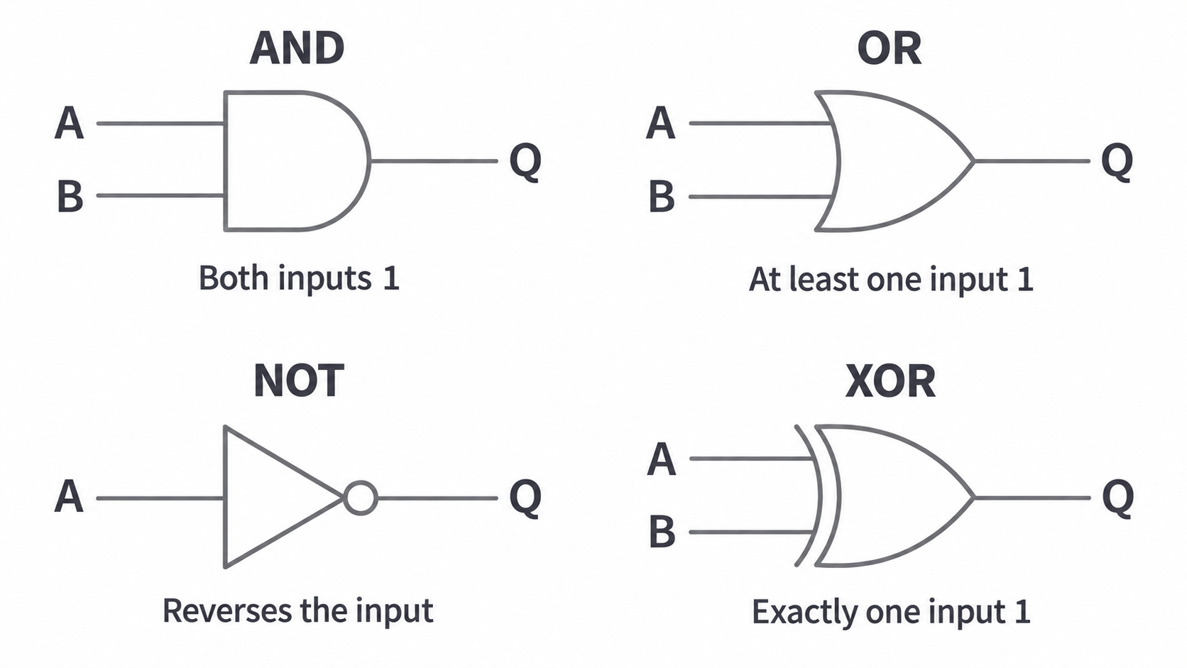
Gate symbols represent these same operations as components. Wires carry logical states from inputs on the left to the output on the right. A NOT gate has a small output bubble for inversion; the extra curved line on the input side distinguishes XOR from OR.
[DIAGRAM: Conventional symbols and output conditions for AND, OR, NOT and XOR; asset_slug: gate-symbols; caption: Four mandatory gates with their distinct output conditions.]
Building a complete truth table
A truth table lists every possible input combination and the corresponding output, rather than a selection of convenient examples.
With independent Boolean inputs there are combinations. Two inputs require four rows; three require eight. List them in binary counting order to avoid omissions. Either 0/1 or false/true is usable if the convention is explicit and consistent.
| 0 | 0 | 0 | 0 | 0 |
| 0 | 1 | 0 | 1 | 1 |
| 1 | 0 | 0 | 1 | 1 |
| 1 | 1 | 1 | 1 | 0 |
Continue this lesson.
You’re previewing NovaLearn without an account. Create a free account to read the rest.
Create free account