1.4.3 - Adders and D-type flip-flops
Logic gates can calculate the bits of a sum, while clocked storage retains a bit for later use. You will derive half and full adders, connect carry between bit positions, and trace the behaviour of a D-type flip-flop at explicitly stated clock edges.
Adding two bits with a half adder
A half adder adds two single-bit inputs and produces a sum bit and carry bit .
The carry has weight 2 and the sum has weight 1, so the two-bit result is , with numerical value . Here the plus in this numerical check is ordinary addition; the gate operations below use Boolean symbols. For , binary 10 means , not two separate sum bits equal to 1.
| Numerical check | ||||
|---|---|---|---|---|
| 0 | 0 | 0 | 0 | 0 |
| 0 | 1 | 1 | 0 | 1 |
| 1 | 0 | 1 | 0 | 1 |
| 1 | 1 | 0 | 1 | 2 |
The sum is true for exactly one true input, so . The carry is true only when both inputs are true, so . OCR's underlined vee , XOR and represent the exclusive operation; ordinary OR would give an incorrect sum bit for inputs 1,1.
To draw the half adder, branch each input to a two-input XOR gate and a two-input AND gate. Label the XOR output and the AND output . A branch distributes the same signal; it does not add a new input bit. The circuit has two independent inputs and therefore four truth-table rows.
A half adder has no carry-in input. Its carry output can pass a value onward, but it cannot include a carry received from a previous bit position. This distinction explains why a half adder alone is insufficient for an arbitrary higher column of a multi-bit addition.
Including carry-in with a full adder
A full adder adds three single-bit inputs: and a carry-in .
It still produces just a sum bit and carry-out bit. Their numerical check is . The possible total is 0,1,2 or 3, represented as 00,01,10 or 11.
| 0 | 0 | 0 | 0 | 0 |
| 0 | 0 | 1 | 1 | 0 |
| 0 | 1 | 0 | 1 | 0 |
| 0 | 1 | 1 | 0 | 1 |
| 1 | 0 | 0 | 1 | 0 |
| 1 | 0 | 1 | 0 | 1 |
| 1 | 1 | 0 | 0 | 1 |
| 1 | 1 | 1 | 1 | 1 |
A full adder can be built from two half-adder stages and an OR gate. The first stage adds , producing intermediate sum and carry . The second stage adds , producing final sum and carry . Either carry makes the final carry-out true:
[DIAGRAM: A full adder using two XOR gates, two AND gates and OR; asset_slug: full-adder; caption: Intermediate P, G and H connect the two half-adder stages to the final sum and carry-out.]
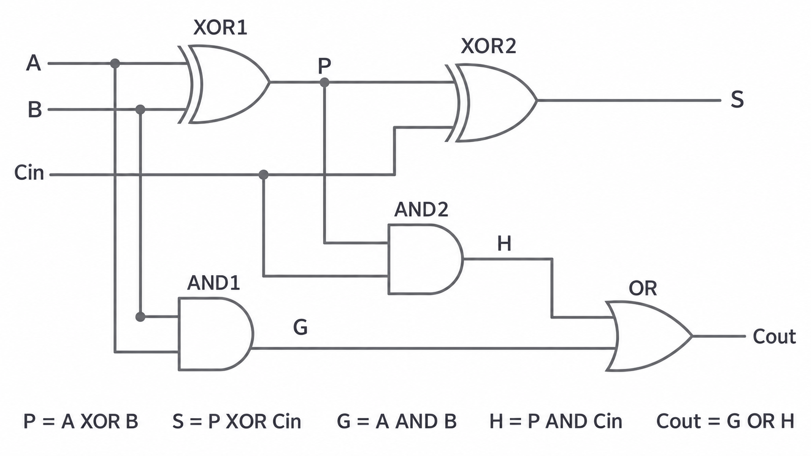
Read the diagram by following the labelled wires. XOR1 makes ; AND1 makes ; XOR2 uses for ; AND2 makes ; OR combines for carry-out. Connection dots mark branches; crossing wires without dots are not connected.
For , , so , representing total 3. Carry-out is also described by the majority expression : it is 1 when at least two inputs are 1. The sum is 1 for an odd number of true inputs. Both descriptions agree with all eight rows.
Carrying between binary columns
A multi-bit adder connects each column's carry-out to the next more significant column's carry-in.
In a ripple-carry adder, this dependency propagates from the least significant bit towards the most significant. The first column can use a half adder if no incoming carry is needed; the later columns need full adders because each must include the previous column's carry. Alternatively, full adders can be used throughout with the initial carry-in fixed to 0.
Continue this lesson.
You’re previewing NovaLearn without an account. Create a free account to read the rest.
Create free account