4.1.8 - Bus, star and mesh topologies
The shape of a network changes what happens when a cable fails, a device is added or reliability matters most. This lesson makes bus, star and mesh structures easy to recognise and gives you a precise way to justify which one fits a situation.
Reading network topologies
Network topology
The arrangement of the nodes in a network and the links between them.
A node is a device or connection point on a network. A link is a wired or wireless connection between nodes. In a topology diagram, circles or device symbols represent nodes and lines represent links. The lines show the available connections; they do not prove that data always travels along every line.
The defining patterns are:
- bus: all end devices connect to one shared main cable, with a terminator at each end;
- star: every end device has a separate link to one central connecting device;
- mesh: nodes have several interconnections, providing more than one possible path in at least part of the network.
[DIAGRAM: asset_name: Comparing bus, star and full mesh structures; asset_slug: 4_1_8_bus_star_and_mesh_topologies__diagram_01; recommended_method: image_gen; description: A monochrome three-panel network topology diagram. The BUS panel has four end-device nodes connected by short separate drop lines to one horizontal backbone, with a short perpendicular terminator bar at each end of the backbone and the exact label Terminator beneath each end, but no central device. The STAR panel has five end-device nodes, each joined by exactly one separate line to a centre node labelled Central device, with no direct links between end devices. The FULL MESH panel has four nodes A, B, C and D with exactly six undirected links AB, AC, AD, BC, BD and CD, so every pair is directly connected. Include the exact panel headings BUS, STAR and FULL MESH, the exact label Backbone on the bus cable, and the exact label Central device inside the star centre. Use no arrows and do not imply data-flow direction.]
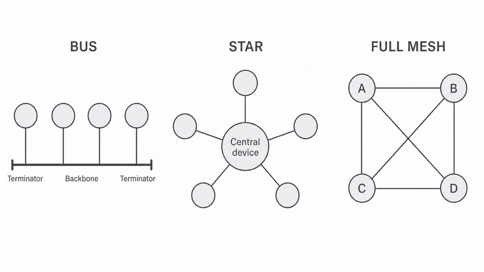
The central node in the star is usually a switch or hub. Its position does not make it a server: a server is defined by the services it provides, not by where it appears in a topology.
Recognise a topology from its connection pattern, not just from the rough shape of the drawing.
Bus topology
Bus topology
A network topology in which every node connects to one shared main cable, called the bus or backbone, with a terminator at each end of the cable.
The backbone is the common communication path. Each terminator absorbs signals when they reach a cable end, preventing reflected signals from interfering with later communication.
This structure gives a bus topology some useful characteristics:
- it can use less cable than giving every device a separate link to a central device;
- it needs no central connecting device, so a small network can have a low initial hardware cost;
- failure of one attached computer does not, by itself, mean that the backbone has failed.
The shared cable also creates limitations:
- the backbone is a single point of failure: damage to it can disrupt communication for several or all nodes;
- a fault can be difficult to isolate because many nodes depend on the same cable;
- adding a node may require the shared cable to be altered or the network to be interrupted;
- all nodes share the same communication path, so increasing the number of devices and the traffic can create contention and reduce performance;
- all attached nodes can see traffic placed on the shared medium, which creates a greater risk of data being observed by another node.
Worked failure example
A ticket office connects four computers and one printer to a bus. If only the printer fails, the four computers may still use the intact backbone. If the backbone is cut, however, the shared path is broken and several devices can no longer communicate. The important distinction is attached-node failure versus backbone failure.
Star topology
Star topology
A network topology in which every end device has its own link to one central connecting device, commonly a switch or hub.
Communication between end devices goes through the central device. Because the links are separate, a star behaves differently from a bus when faults occur:
- failure of one end device or its link normally isolates only that device;
- each link can be checked separately, making faults easier to locate;
- a new device can usually be added on a new link without changing existing links, provided the central device has a suitable spare connection;
- the number of directly attached devices is limited by the central device's available connections, so further expansion may require a larger or additional central device;
- more cable is needed than for a simple bus, and the central device adds cost;
- the central device is a single point of failure: if it fails, the attached devices cannot communicate through it;
- the central device's capacity can limit performance if it cannot process the traffic quickly enough.
When the centre is a switch, it normally sends traffic only along the link towards the intended recipient. This reduces unnecessary traffic exposure and can improve performance compared with one shared bus. A hub does not provide the same traffic isolation, so the star arrangement by itself does not guarantee security.
Worked failure example
Six library computers connect to a central switch. If the cable from computer 4 is cut, computer 4 is disconnected but the other five links remain intact. If the switch fails, none of the six computers can communicate through the network. Saying "a single failure stops a star" is therefore too vague: the consequence depends on which component fails.
Continue this lesson.
You’re previewing NovaLearn without an account. Create a free account to read the rest.
Create free account