3.4.2 - Logic gates and truth tables
Recognise AQA's NOT, AND, OR and XOR symbols and construct their truth tables. Use 0 and 1 to reason about conditions instead of guessing from a gate's name.
NOT, AND, OR and XOR gates
A logic gate applies a Boolean rule to its input values to produce an output of either 0 or 1.
In a condition, 0 can represent false and 1 true. In a circuit, these values represent the two signal states. Follow the input wires from the left and read the output on the right.
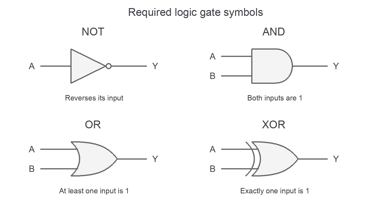
NOT has one input and an inversion circle. AND has a flat input edge. OR has a curved input edge. XOR has the extra curved line behind the OR shape.
NOT reverses its one input: 0 becomes 1 and 1 becomes 0. The small circle at the output indicates inversion. AND outputs 1 only when both inputs are 1. OR outputs 1 when at least one input is 1, including when both are 1. XOR, exclusive OR, outputs 1 when exactly one of its two inputs is 1.
For a door with two required permissions, AND models the need for both. For a warning triggered by either of two sensors, OR is appropriate even if both trigger together. XOR would instead switch off when both inputs are 1. This distinction is why the extra curve on the symbol matters.
Only these four gates are required here. NAND and NOR are not required by this specification.
Continue this lesson.
You’re previewing NovaLearn without an account. Create a free account to read the rest.
Create free account