3.1.1 - Designing, representing and tracing algorithms
An algorithm becomes easier to check when you identify what it receives, what it does and what it produces. Pseudocode, flowcharts and trace tables help you turn a problem into a method and explain why the method works.
Inputs, processing and outputs
A useful first step in designing an algorithm is to identify its inputs, processing and outputs.
| Element | Meaning | Example: calculate the price of £4 tickets |
|---|---|---|
| Input | Data supplied to the algorithm | The number of tickets requested |
| Processing | Operations performed on that data | Multiply the number by 4 |
| Output | Results produced by the algorithm | The total price |
The same distinction applies to other contexts. A temperature-alert system receives a temperature, compares it with a limit and produces a warning or an all-clear message. The comparison is processing; the warning is output. An output need not be a number.
Work systematically from the brief. Decide the required result, identify the data needed to produce it, and state any assumptions. Then design the processing steps in a useful order. For example, a work queue must complete the requested number of jobs and display Done afterwards. Assume the input is a valid whole number of zero or more. The input is the initial number of jobs; the processing completes a job and reduces the remaining count repeatedly; the output is the final message.
Locate each element in this simpler price algorithm:
tickets ← USERINPUT
price ← tickets * 4
OUTPUT price
The first line is input. The second is processing. The third is output. Assigning the calculated result to price does not display it: output happens only when the output instruction is reached.
Pseudocode and flowcharts
Pseudocode describes the steps in readable text, while a flowchart uses symbols and arrows to show the order in which steps are followed.
AQA uses a consistent pseudocode style in supplied examination material. You must be able to read that style. When a question asks you to write an answer, follow its stated response form: pseudocode, program code or a flowchart. If pseudocode is permitted, a clear, consistent and unambiguous alternative style is acceptable.
Here is a version of the work-queue algorithm. The variable completed counts the jobs completed, so we can inspect the processing. The arrow ← means assignment; > means greater than. A WHILE loop repeats its indented body while its condition is true and stops when the condition becomes false.
jobs ← USERINPUT
completed ← 0
WHILE jobs > 0
    completed ← completed + 1
    jobs ← jobs - 1
ENDWHILE
OUTPUT 'Done'
For an input of 3, the body runs three times. Increasing completed records one completed job, and reducing jobs records one fewer job remaining. Eventually jobs becomes 0, so the loop stops. For an input of 0, the condition is false immediately: no job is completed and Done is still output.
The flowchart below shows the same queue method at the task level: “Complete one job” stands for carrying out the job before reducing the remaining count. The symbol key also includes a predefined-process symbol, which can represent a separately defined subroutine.
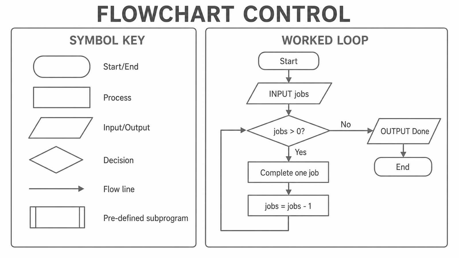
The right-hand flowchart inputs the remaining-job count, follows the Yes branch while jobs > 0, completes one job and subtracts one before returning to the decision. Its No branch outputs Done and ends.
An oval marks Start or End, a rectangle marks processing, a parallelogram marks input or output and a diamond marks a decision. Arrowheads give the flow direction. Label the decision exits so that the reader can tell which route is taken. The diagram's jobs = jobs - 1 process means “replace jobs by jobs minus one”; in AQA pseudocode we write that assignment as jobs ← jobs - 1.
Notice that the loop returns to the decision, not to the input. Re-reading the original number every time would reset the work instead of reducing the remaining count. In your own flowchart, choose the symbol for what a step does and connect every possible route coherently.
A program implements this method in a language. In the Python Study demonstration, while has a colon and indentation defines its body. The final extra print shows the completed count so you can inspect the result. It is a Python demonstration, not the pseudocode answer required below.
Python demonstration: completing a work queue
{"code":"jobs = 3\ncompleted = 0\nwhile jobs > 0:\n completed = completed + 1\n jobs = jobs - 1\nprint('Done')\nprint('completed =', completed)\n","instructions":"Predict how many jobs are completed and when Done is displayed. Run the program. Change only jobs = 3 to jobs = 0, predict whether the loop body runs, then run again. Use this zero-job case to check that the method finishes correctly without doing an extra job."}
Tracing and finding purpose
A trace follows an algorithm one instruction at a time and records how its values change. It provides evidence about the algorithm's behavior and helps you work out its purpose.
For the queue pseudocode above, use the input 3. Each row below states the point at which the values are recorded; a trace question may prescribe a different layout, which you should follow.
| Point in execution | jobs | completed | Next test jobs > 0 | Output so far |
|---|---|---|---|---|
| After input and initialisation | 3 | 0 | True | None |
| After first loop body | 2 | 1 | True | None |
| After second loop body | 1 | 2 | True | None |
| After third loop body | 0 | 3 | False | None |
| After the output instruction | 0 | 3 | No further test | Done |
Read each assignment using the current value. In the first body, completed ← completed + 1 uses 0 to produce 1; jobs ← jobs - 1 uses 3 to produce 2. The third body leaves zero jobs, so the next test fails. There is no fourth body and no negative remaining-job count.
Visual inspection gives the same explanation. completed starts at zero and gains one each time; jobs loses one each time. Together with the condition, this tells us the purpose: complete the initial number of jobs, track how many were completed and signal that the queue has finished. A purpose statement describes the overall task, rather than simply repeating “it adds and subtracts”.
Tracing also reveals faults. If the decrement were omitted, jobs would stay at 3 and the condition would remain true indefinitely. If the condition were jobs ≥ 0, the body would also run when no jobs remained, creating an extra completion before stopping at −1. These observations justify the original condition and update.
Test a design against expected behavior, then refine it if the observation differs. For this method, input 3 should complete three jobs, input 1 one job and input 0 none. The sandbox's zero-job modification checks an important case, rather than merely changing a number for no purpose. A later program may combine such processing with stored records or a device's inputs; explaining the algorithm still depends on the data and operations actually used in that problem.
Design from the required result, represent the steps clearly and trace the current state. The same reasoning helps you check a program and justify a correction.