15-16 - Projectile Motion and Free-Body Diagrams
This lesson covers rows 15-16: resolving projectile motion into horizontal and vertical components, and drawing free-body diagrams for objects in motion. The important idea is that the two components share the same time while the forces decide the acceleration.
Two Motions, One Clock
Picture a ball rolling off the edge of a bench. After it has left the bench, suppose air resistance is negligible. The ball is then a projectile moving freely under gravity: it is no longer being pushed by the bench, the hand, or the launcher. Its path is curved, but the useful trick is to stop trying to solve "the curve" all at once.
Use two perpendicular descriptions of the same motion:
- horizontal motion, along the
xaxis - vertical motion, along the
yaxis
The two descriptions share the same time t. That is the hook that keeps the problem together. The horizontal displacement does not set the vertical acceleration, and the vertical fall does not use up horizontal velocity. They are independent components of one motion, connected by the same clock.
For a projectile freely moving under gravity near Earth's surface:
- horizontal acceleration is zero if air resistance is ignored
- vertical acceleration is
g = 9.81 m s^-2downward - horizontal velocity is constant
- vertical velocity changes because gravity acts vertically
If you choose upwards as positive, then a_y = -9.81 m s^-2. If you choose downwards as positive, then a_y = +9.81 m s^-2. Either convention is fine, but you must use it consistently.
For a horizontal launch from a bench, the vertical initial velocity is u_y = 0 even though the object has a non-zero horizontal speed. That sentence is where many projectile errors begin or end.
Tempting wrong idea: "A faster horizontal throw stays in the air for longer."
Correct contrast: for two objects leaving the same height with the same initial vertical velocity, the time of flight is set by the vertical motion. A faster horizontal throw travels further during that time, but it does not delay the fall in the ideal model.
In Edexcel language, an "explain" answer here needs the link: no horizontal effect on vertical acceleration, so vertical motion determines the fall time.
Worked Example: Horizontal Launch
A ball leaves a bench horizontally at 3.20 m s^-1. The bench top is 1.25 m above the floor. Air resistance is negligible. Determine the time taken to reach the floor and the horizontal distance from the bench.
First decide what each axis knows.
Vertical information:
- choose downwards as positive
s_y = 1.25 mu_y = 0a_y = 9.81 m s^-2tis unknown
Horizontal information:
u_x = 3.20 m s^-1a_x = 0xis unknown- the time is the same
t
Decision point 1: use the vertical motion to find the time, because the vertical displacement and vertical acceleration are known. Do not put 3.20 m s^-1 into the vertical equation. That is the horizontal speed.
Use:
s_y = u_y t + 1/2 a_y t^2
Substitute:
1.25 = 0 + 1/2(9.81)t^2
1.25 = 4.905t^2
t^2 = 1.25 / 4.905
t = 0.505 s
Decision point 2: take the positive square root because time after launch is positive.
Now use the horizontal motion:
x = u_x t
x = 3.20 x 0.505
x = 1.62 m
Decision point 3: the horizontal equation is simple because a_x = 0. The ball keeps the same horizontal velocity while gravity changes only the vertical velocity.
Final answer: the ball reaches the floor after 0.505 s and lands about 1.62 m from the bench.
If an Edexcel item says "determine", your answer needs this quantitative route: component choice, substitution, units and a sensible rounded result. If it says "show that the time is about 0.50 s", keep the unrounded value 0.505 s in the working before rounding to the stated figure.
Launch at an Angle
For a launch at an angle, the first move is not to search for a new projectile formula. The first move is to split the initial velocity into components.
If a projectile is launched with speed u at angle theta above the horizontal:
u_x = u cos(theta)
u_y = u sin(theta)
Those equations are just vector resolution from the previous lesson, now used as the starting line for projectile motion.
Worked example: a ball is kicked from ground level at 12.0 m s^-1 at 35.0 degrees above the horizontal. It lands at the same height. Air resistance is negligible. Determine the time of flight and the horizontal range.
Resolve the launch velocity:
u_x = 12.0 cos(35.0 degrees) = 9.83 m s^-1
u_y = 12.0 sin(35.0 degrees) = 6.88 m s^-1
Decision point 1: use u_y, not the full 12.0 m s^-1, in the vertical SUVAT equation. A one-axis equation needs one-axis quantities.
Choose upwards as positive:
- launch and landing heights are the same, so
s_y = 0 u_y = +6.88 m s^-1a_y = -9.81 m s^-2
Use:
s_y = u_y t + 1/2 a_y t^2
0 = 6.88t - 4.905t^2
0 = t(6.88 - 4.905t)
This gives two roots:
t = 0, the launch instant6.88 - 4.905t = 0, sot = 1.40 s
Decision point 2: the non-zero root is the landing time. The zero root is not a mistake; it is the starting instant.
Now use horizontal motion:
x = u_x t
x = 9.83 x 1.40
x = 13.8 m
Decision point 3: the top of the path is not the landing time. At the top, v_y = 0, but the projectile is still moving horizontally.
This is why drawing or imagining the component velocities matters: a projectile can have zero vertical velocity at one instant while still having a horizontal velocity.
Free-Body Diagrams as Force Models
A free-body diagram is not a sketch of the motion. It is a force model for one chosen body.
[DIAGRAM: asset_name: Projectile and free-body force models; asset_slug: 005_projectiles_and_free_body_diagrams__diagram_01; recommended_method: image_gen; description: Two-panel monochrome diagram. Left panel shows a projectile moving under gravity with a dotted parabolic path, horizontal velocity arrow, downward g arrow, and a separate particle free-body diagram showing weight only. Right panel shows an extended beam free-body diagram with upward support reaction arrows and downward weight/load arrows at distinct lines of action.]
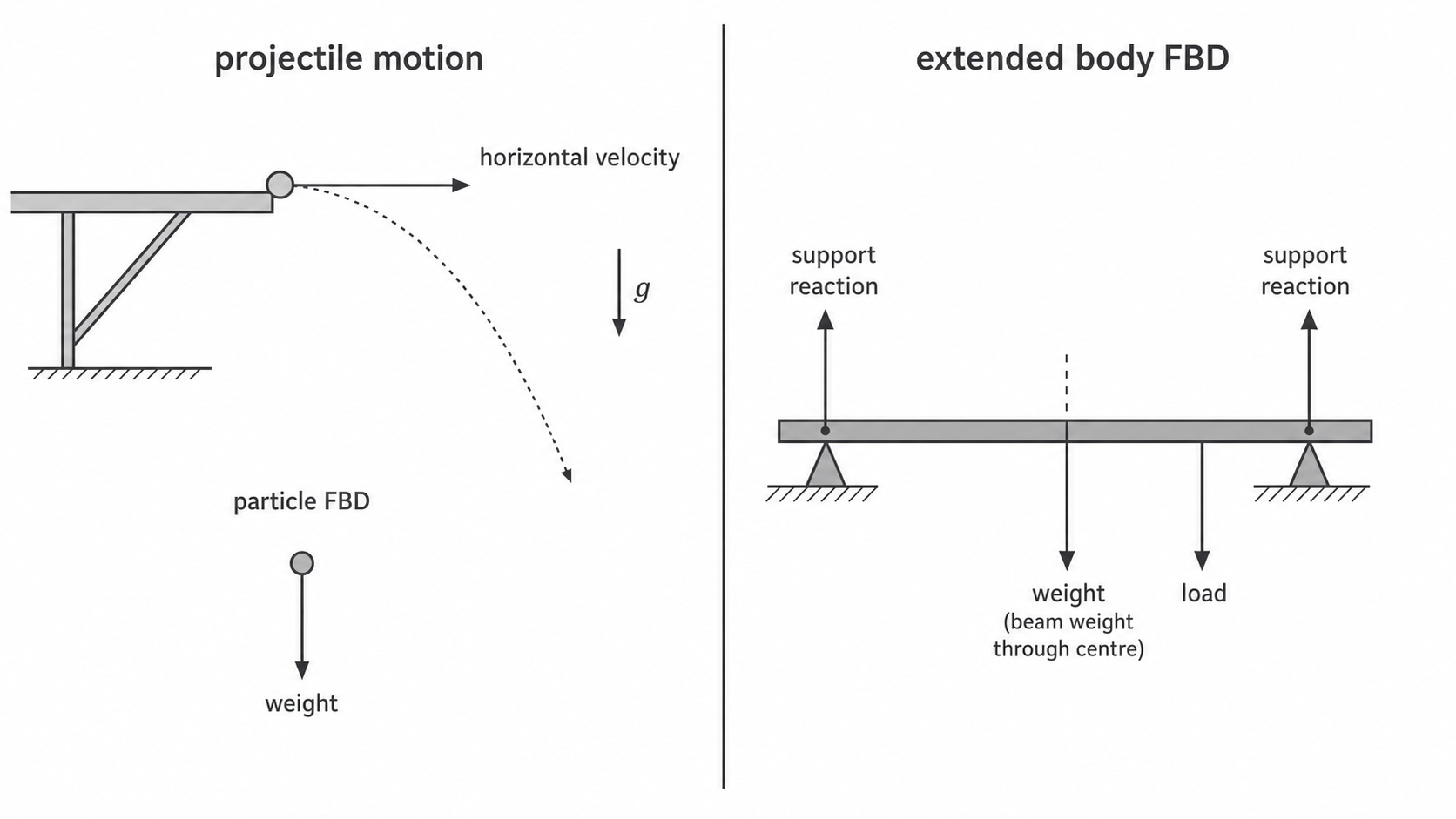
Use this routine every time you draw one:
- Choose the body or system.
- Decide whether it can be treated as a particle or whether it is an extended rigid body.
- Draw only the external forces acting on that chosen body.
- Label each force, including its direction.
- For an extended rigid body, keep where the force acts and its line of action.
For a particle, the body can be represented by a dot because the position of each force on the body is not being used. For an extended rigid body, such as a beam or plank, the force positions matter for interpretation. The moments calculation belongs later in the course; here the important skill is drawing and reading the force model correctly.
The projectile example is deliberately stark. Once the ball has left the hand, bench or launcher, and air resistance is ignored, the only force acting on it is its weight, labelled W, downward. The velocity arrow is not a force. The curved path is not a force. There is no continuing forward "throw force" after contact has ended.
For the Edexcel command word "draw", credit depends on the diagram itself: the chosen body must be clear, force arrows must be in the correct directions, labels must be meaningful, and an extended body must keep the relevant positions of the forces. A beautiful sketch with the wrong forces is still the wrong model.
Interpreting Force Diagrams
Drawing a free-body diagram is only half the skill. The other half is interpreting what the diagram says about the physical model.
For the freely moving projectile:
- the FBD has weight downward only
- the acceleration is therefore vertical in the projectile model
- there is no horizontal acceleration in the ideal model
- the horizontal velocity stays constant while the vertical velocity changes
The formal sum F = ma equation comes in the next lesson. Here, use the diagram qualitatively: the force model tells you which axis has acceleration.
For an extended rigid body, interpretation starts with the system boundary. Suppose a rigid plank rests on two supports and a box sits on the plank.
If the chosen body is the plank only, the external forces on the plank are:
- upward contact force from the left support
- upward contact force from the right support
- downward weight of the plank, acting through its centre of gravity
- downward contact force from the box on the plank, acting at the box's contact position
If the chosen system is plank plus box, the force from the box on the plank is internal to the system and is not drawn. Instead, the weight of the box is an external gravitational force on the system. The same real situation can lead to different correct FBDs because the chosen body is different.
Tempting wrong idea: "Forces on the support should go on the plank's FBD."
Correct contrast: a free-body diagram for the plank shows forces acting on the plank. Forces exerted by the plank on the supports act on different bodies, so they do not belong on that FBD.
For the command word "interpret", do more than name arrows. State what body the diagram represents, what interactions each arrow represents, and what physical conclusion follows. In a projectile question, that conclusion might be "use vertical SUVAT to find the time" or "horizontal velocity remains constant in the model".
Video, Graph and Exam Transfer
Projectile motion is a natural place to use video or strobe data. Each frame is a timestamp. If the frame interval is constant, the horizontal and vertical positions can be read at equal time intervals.
For a horizontal launch:
- equal horizontal spacing between successive positions supports constant horizontal velocity
- increasing vertical spacing supports increasing vertical speed
- the same time values must be used for both axes
If downwards is positive and the object is launched horizontally, u_y = 0, so:
s_y = 1/2 g t^2
That means a graph of vertical displacement s_y on the y-axis against t^2 on the x-axis should be a straight line through the origin in the ideal model. Its gradient is:
gradient = s_y / t^2 = 1/2 g
So:
g = 2 x gradient
This is not a separate practical to memorise. It is the independence model turned into a data method.
Practical details matter because a video is not perfect physics:
- calibrate the distance scale using a metre rule or known length in the plane of motion
- use the frame rate to find the time interval
- mark the same point on the object in each frame, such as its centre
- keep the camera square-on to reduce parallax
- use several points and a best-fit line rather than relying on one noisy frame
- quote values to sensible precision based on the frame and scale resolution
Edexcel command-word transfer:
- "Plot" means suitable axes, units, scales, accurate points and a best-fit line if needed.
- "Determine"
gfrom video data means a quantitative route such as a gradient andg = 2 x gradient. - "Explain" independence means linking the force model to vertical acceleration and horizontal constant velocity.
- "Show that" means carrying enough precision before rounding to the value in the question.